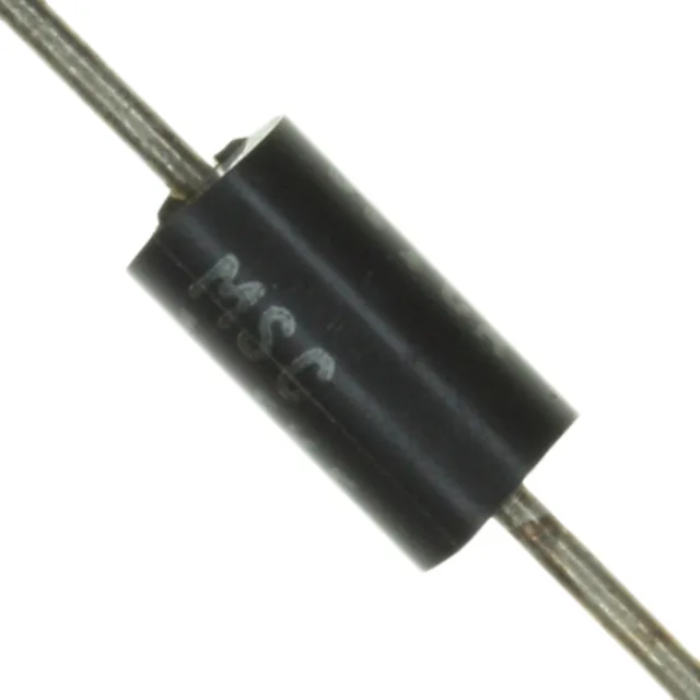
1.5 kW peak pulse power, 9.4 V standoff — Zener TVS in DO-201AA axial
The 1.5KE11AE3/TR13: The 9.4 V reverse standoff voltage means it begins conducting only when the line exceeds that threshold — normal 5 V or 9 V rails ride below it without leakage. Clamping is specified at 15.6 V maximum at the 96 A peak pulse current, so a transient that would otherwise reach 30 V is clipped to under 16 V. The DO-201AA axial-lead package (CASE-1) is a through-hole form factor common in power-supply input protection, telecom line cards, and industrial control boards where the board can accommodate a leaded part. The -65°C to 150°C junction temperature range covers military and automotive under-hood thermal profiles without derating.
Obsolete — sourcing through independent distribution
Microsemi has marked the 1.5KE11AE3/TR13 as obsolete. No official successor order code is recorded. The Tape & Reel packaging (TR suffix) suits automated pick-and-place for through-hole axial parts with formed leads.
Clamping voltage and pulse current — what the ratings mean for the protection decision
The 10.5 V minimum breakdown voltage and 15.6 V maximum clamping voltage define the protection window. A 12 V bus sees the TVS avalanche at roughly 10.5 V and clamp at 15.6 V — the downstream equipment must survive that clamp level for the 10/1000 µs pulse duration. The 96 A peak pulse current at that waveform means the device can absorb a 1500 W pulse without failing short; the actual energy depends on the pulse shape and duration. The unidirectional configuration biases the Zener junction for positive-going transients; a reverse-connected TVS in series would be needed for bidirectional protection on AC-coupled lines.