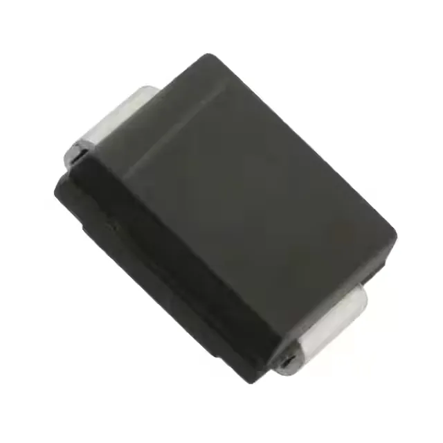
1500 W peak pulse, 90 V rail protection
The SMCJ90A-13-F: Its 146 V clamping voltage at 10.3 A peak pulse current (10/1000 µs waveform) defines the voltage the downstream circuitry must survive during a surge event — a 90 V supply bus sees the clamp engage at 100 V breakdown minimum and hold the line at 146 V worst case. Single unidirectional channel means it protects one polarity; the cathode band on the DO-214AB SMC package marks the grounded side. The -55°C to 150°C junction temperature range covers industrial cabinet ambient and under-hood thermal profiles without derating the 1.5 kW peak pulse rating.
Clamp voltage and peak current — the surge budget
The 146 V maximum clamping voltage at 10.3 A peak pulse current sets the upper bound on the transient the protected load sees. For a 90 V nominal rail, this clamp voltage leaves a 56 V margin above the operating level — enough headroom for most 100 V-rated downstream components to survive a lightning-induced surge or inductive load dump without secondary protection. The 100 V minimum breakdown voltage ensures the TVS does not conduct at the 90 V steady-state rail, yet triggers early enough to prevent the transient from exceeding the 146 V clamp. Power line protection is marked as 'No' — this is a signal- or DC-power-rail protector, not a mains AC surge suppressor.
Active production, standard footprint
Housed in the DO-214AB (SMC) surface-mount package, the footprint is shared across the SMCJ family, so a single PCB layout serves multiple voltage variants. The Tape & Reel (TR) and Cut Tape (CT) packaging options suit both volume production and prototype runs.