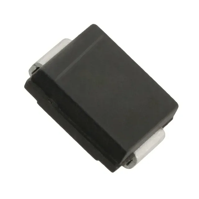
What the 1500 W peak pulse rating means for your protection design
The SMCJ110CA-13-F: That 1500 W figure is the product of the clamping voltage (177 V max) and the peak pulse current (8.4 A). For a 110 V rail, the 177 V clamp means the TVS holds transients well below the typical 200 V abs-max of downstream DC-DC converters and linear regulators, giving the board a clean voltage-limiting ceiling. The 110 V reverse standoff voltage (working voltage) means the diode draws negligible leakage below 110 V DC — it stays invisible to the circuit until a transient pushes the line above the breakdown threshold (122 V min). This is the right pick for 100–110 V DC buses, 48 V telecom rectifiers stacked in series, or 72 V battery banks where the nominal rail sits below 110 V.
Housed in the DO-214AB (SMC) package, this TVS sits in the standard SMC footprint — the same pad layout used by 1500 W SMCJ-series diodes across multiple manufacturers. The SMC body is larger than the SMA/SMB siblings, which means the solder joint and copper pad area on the PCB must handle the thermal pulse energy during a 10/1000 µs surge. A 2 oz copper pour under the cathode tab helps spread the heat and keeps the junction below the 150 °C limit. The -13-F suffix indicates the reel quantity (typically 3000 pieces per reel for SMC).
The junction rating gives margin for self-heating during repetitive surge events.