Clamp voltage and pulse current — the real protection envelope
The SMBJ51A-13: The 82.4 V clamp sets the upper bound on what the protected node sees during a surge. For a 51 V rail, this means the TVS holds the transient to about 1.6× the nominal voltage — tight enough that a downstream 100 V-rated DC-DC converter or linear regulator survives a 600 W pulse without avalanche breakdown. The 7.3 A peak pulse current rating at the standard 10/1000 µs waveform is the current the device can shunt without exceeding its thermal limit. For shorter pulses (8/20 µs, common in ESD testing), the peak current capability is significantly higher — the 600 W rating scales inversely with pulse width per the datasheet's derating curve. At elevated temperatures, the breakdown voltage shifts slightly (typically +0.1%/°C for Zener-type TVS), so the 56.7 V minimum breakdown at 25°C rises to about 63 V at 150°C, which still leaves margin below the 82.4 V clamp.
DO-214AA SMB — footprint and reflow
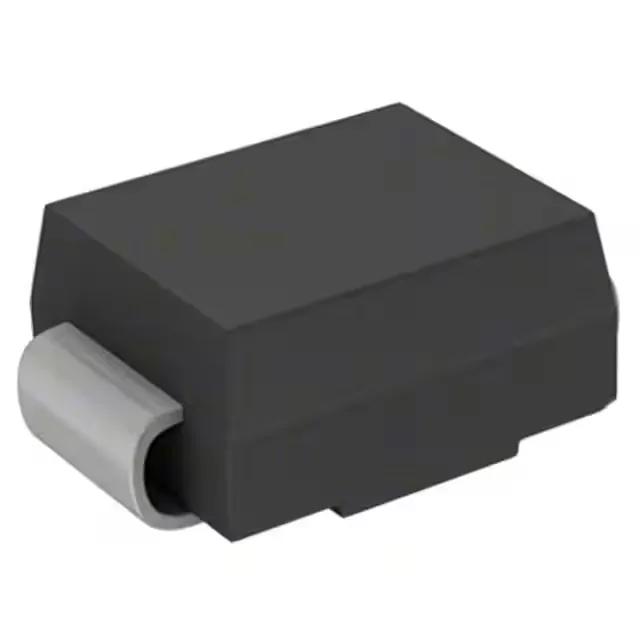
Housed in the DO-214AA (SMB) surface-mount package, the SMBJ51A-13 occupies a standard 4.6 mm × 5.4 mm footprint with a 2.3 mm height. The package is compatible with reflow soldering profiles per JEDEC J-STD-020; the typical peak reflow temperature is 260°C for 10 seconds. No special bake-out is required for moisture-sensitive level (MSL) 1-rated devices. The unidirectional configuration means the cathode band marks the grounded side — the anode connects to the protected rail. For a 51 V rail, the TVS sits reverse-biased in normal operation, drawing only leakage current (typically < 1 µA at 25°C).