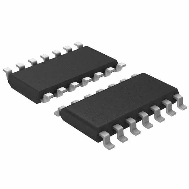
Dual comparator with latch – what it does for the BOM
The MAX9202ESD+T is a dual comparator with latch, meaning each channel can hold its output state on a latch-enable signal. This is the spec that matters if you are digitising a zero-crossing or a sampled threshold — the latch eliminates output chatter during the hold period. Outputs are TTL-compatible, so the comparator drives directly into a logic gate input without a level translator. The supply range covers 4.75 V to 10.5 V single-supply or ±2.375 V to ±5.75 V split-supply, which fits common 5 V and ±5 V rails.
Parametric deep-dive – what the numbers mean for your threshold design
Input offset voltage is 4 mV max at ±5 V — that sets the DC accuracy floor for your trip point. If you need better than 4 mV, you will need to calibrate or choose a precision comparator. Input bias current is 5 µA max at ±5 V, which is moderate; for high-impedance sources, account for the voltage drop across the source resistance. Common-mode and supply rejection are both 86 dB typ. That means a 1 V shift in the supply or common-mode voltage changes the threshold by about 50 µV — good enough for most industrial threshold circuits, but not for microvolt-level sensing. Quiescent current is 4 mA max across both comparators — about 2 mA per channel. That is reasonable for a general-purpose comparator but not ultra-low-power; if your system runs on a coin cell, consider a micropower comparator instead.
Sourcing and lifecycle – active production, no obsolescence risk
That means you can design it into a new BOM without worrying about a sudden last-time-buy. The part is supplied in Tape & Reel (TR) or Cut Tape (CT) options, both ROHS3 compliant. For volume production, the TR reel is the standard procurement path; CT is available for prototypes or small runs.
Package and board integration – 14-SOIC footprint
The MAX9202ESD+T is housed in a 14-SOIC (0.154", 3.90 mm width) surface-mount package. The 1.27 mm pitch is layout-friendly — two-layer boards can route the fan-out without vias. The supplier device package is 14-SOIC, so the land pattern matches any standard SOIC-14 footprint. No AEC-Q grade is listed, so this part is not qualified for automotive under-hood use.