40 ns propagation delay — what it buys you
The MAX9142EKA+T: That 40 ns figure sets the upper bound on how fast the output can change state after the input crosses the threshold — for a 10 MHz input square wave, the comparator can track edges with roughly 0.04% of the period lost to propagation, which keeps the timing budget intact for most sensor-to-logic interfaces. Hysteresis of 1.5 mV is built in — no external positive feedback resistors needed. This prevents output chatter when the input signal sits near the threshold voltage, particularly on slow-moving analog signals from thermocouples or pressure transducers. The 300 µA maximum quiescent current per channel means the comparator's own draw is negligible in a battery-powered system — a 3.3 V rail can run both channels continuously without eating into the sensor bias budget.
Output stage and input offset
Output type is CMOS push-pull and TTL-compatible — it drives logic inputs directly without a pull-up resistor. The push-pull stage also handles capacitive loads better than an open-drain output, so a short trace to a microcontroller GPIO is fine. That CMRR figure means a 1 V common-mode shift at the inputs produces less than 0.1 mV of apparent offset — relevant when the comparator monitors a differential signal across a long cable run. Maximum input bias current is 0.32 µA at 5 V. For a high-impedance source like a 10 kΩ sensor, the voltage error from bias current is under 3.2 mV — comparable to the offset itself, so a low source impedance is still advisable.
SOT-23-8 package — rework and layout
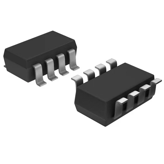
The SOT-23-8 package has no exposed paddle on the top side, so orientation marking is a small dot at pin 1 — verify it under magnification before placement.
Sourced through independent distribution channels.