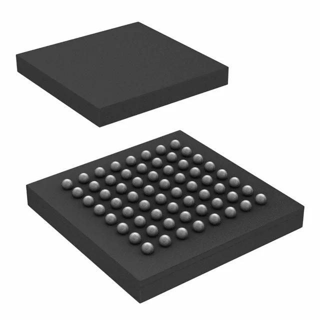
Quad 20 A buck in a 3.41×3.37 mm WLP
The MAX77812AEWB+T: Switching at 2 MHz, the output filter components shrink below what a 500 kHz design needs — the inductor value drops roughly in inverse proportion to frequency, so a 2 MHz switcher uses a smaller, lower-profile inductor that fits the tight keep-out zones around a BGA package. The output is adjustable from 0.25 V up to 1.525 V, which covers the sub-1 V core voltages of modern processors as well as the 1.2 V and 1.5 V rails for DDR memory and I/O banks.
Housed in a 64-WFBGA, WLBGA package (supplier device package 64-WLP, 3.41×3.37 mm), this is a fine-pitch ball-grid array — no hand-soldering in the field. The reflow profile needs a pre-bake if the moisture-sensitive level (MSL) floor has been exceeded; the tape-and-reel packaging (also available as cut tape) keeps the parts dry until the reel seal is broken. No synchronous rectifier is integrated — the low-side diode is external. That means the efficiency curve and the thermal budget depend on the Schottky you pair with it; a 20 A output with a 0.4 V forward drop dissipates 8 W in the diode alone, so the diode footprint and heatsinking matter as much as the regulator layout.
The 85°C ceiling means the part stays within spec in a ventilated enclosure at full load; in a sealed box with no airflow, the junction temperature will climb above ambient by the package thermal resistance times the power dissipation.