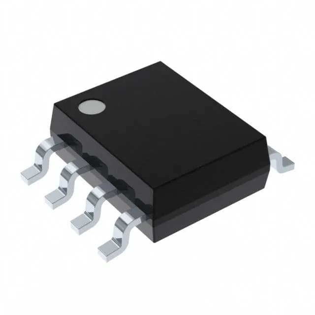
Negative output — the key constraint
The output configuration is Negative, which is the headline feature. Most buck-boost controllers produce a positive output; this one inverts the input to give a negative rail. The control loop and external transistor arrangement are specific to that topology — you cannot simply swap it into a positive-output buck-boost layout. The datasheet application circuit shows the external PMOS/NMOS pair and the inductor connection to ground. If your BOM calls for a negative rail from a positive input, this controller fits directly. If you need a positive output, look at a standard buck-boost or SEPIC controller instead.
Fixed 300kHz, no sync — plan for beat frequencies
The switching frequency is fixed at 300kHz, and the part has no clock sync input. In a single-regulator design that is fine. In a multi-rail system with another switcher running at a different frequency, the lack of sync means you get beat-frequency ripple on the input bus. Keep the layout tight and add enough input capacitance to handle the intermodulation. The 300kHz rate is a reasonable middle ground — efficient enough for most loads, and the external transistor switching losses are manageable.