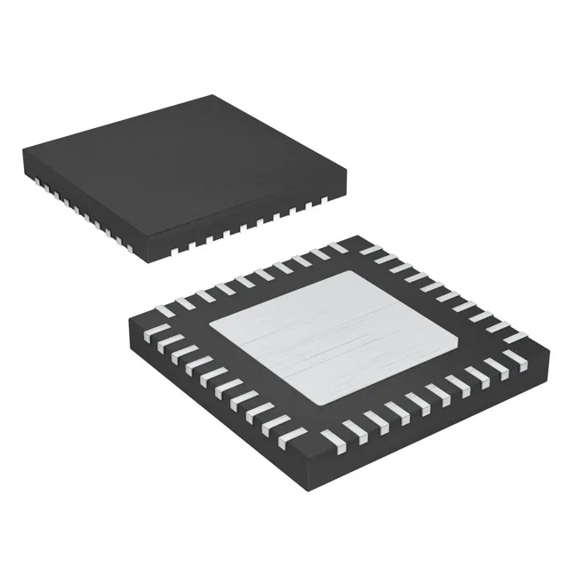
28-port SPI GPIO expander — active production, no second-source flag
The MAX7301ATL+T is a 28-port GPIO expander from Analog Devices, controlled over a 26 MHz SPI bus. It sits in the category of Microcontrollers & Processors (MCU / MPU / DSP) but is purely an I/O peripheral — no onboard MCU core, just 28 push-pull I/O lines that the host processor reads and writes through a 4-wire SPI interface. Each I/O can source 4.5 mA or sink 10 mA, enough to drive LEDs, small relays, or level-translate to a 2.5 V logic domain without external buffers. This is a single-source part; if you need a pin-compatible alternative, the MAX7300 (I²C version) shares the same package but the interface is different, so a board spin is required.
SPI-bus integration — clock rate, interrupt, and the firmware checklist
The SPI clock runs up to 26 MHz, which means a single 32-bit read or write completes in under 1.5 µs at full speed — fast enough to poll all 28 inputs in a 1 kHz control loop without starving the main application. The part has a dedicated interrupt output pin (active-low, open-drain) that asserts when any input configured as a change-of-state detect toggles, so the host does not need to poll the expander at all unless an edge arrives. For a firmware engineer stepping through the boot sequence: the MAX7301 powers up with all I/O configured as inputs with weak pull-ups. The first SPI transaction should write the configuration register to set the desired port direction and output polarity before the host's own I/O pins are released from reset. The datasheet's register map is straightforward — six 8-bit registers for port configuration and data, plus a global shutdown bit that gates all outputs simultaneously.
Package and board-fit — 40-TQFN with exposed pad
The 0.5 mm pitch of the TQFN demands a solder-paste stencil with apertures sized for the pad geometry — a standard NSMD (non-solder-mask-defined) land pattern works.
Supply and temperature — wide-range, industrial-grade
The 4.5 mA source / 10 mA sink per I/O is enough to drive a standard LED at 5 V with a 330-ohm series resistor, or to interface with a 3.3 V CMOS input without level translation — the output high voltage tracks V+ minus about 0.4 V at 4.5 mA load.