Fan-speed controller with dual temperature sensing
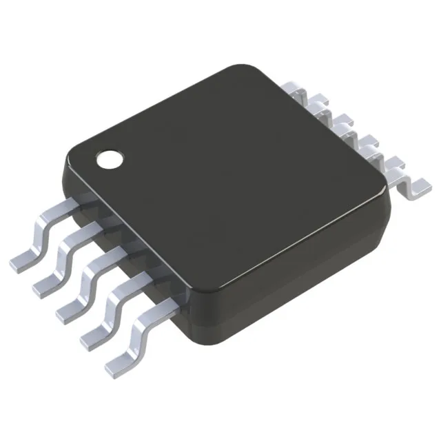
The MAX6645ABFAUB+ from Analog Devices integrates a temperature monitor and fan-speed controller in a single 10-uMAX/uSOP package. It measures its own die temperature and one external diode-connected transistor, combining local and remote sensing into one control loop. Accuracy is ±3.5°C (max) on the local channel and ±3°C (max) on the remote channel — tight enough to set fan-speed ramps based on a hot spot like a CPU core or power-stage die without overshooting the thermal budget.
What the functional blocks mean for your BOM
The part contains an ADC, a PWM generator, and a tachometer counter. The ADC digitises both temperature channels; the PWM generator drives the fan directly from the PWM output pin; the tach counter reads the fan's speed signal to close the loop. This means a single IC replaces a discrete thermistor, comparator, and PWM driver — saving board area and reducing the BOM count for a speed-controlled fan. The operating temperature range covers -40°C to +125°C, matching the industrial temperature grade — suitable for equipment enclosures where ambient air can reach 85°C and the local die runs hotter. The remote sensor input accepts an external diode-connected transistor (typically a 2N3906 or a substrate PNP on an ASIC). The sensing range for the external sensor is -40°C to +125°C, so it can monitor a processor die or a power MOSFET case across the full industrial temperature span.
The 10-TFSOP / 10-MSOP package has a 0.118-inch (3.00 mm) body width and a 0.50 mm lead pitch. The supplier device package is designated 10-uMAX/uSOP. For pick-and-place assembly, order the tape-and-reel variant if available; the tube quantity is typically 50 or 100 pieces depending on the supplier's packaging code.
No official successor or pin-compatible alternative is listed by Analog Devices. If a second-source is needed for a dual-source BOM, the closest functional match is another device in the MAX6645 family with the same package code — confirm the accuracy grade and the PWM frequency range before substituting.