Two 10kΩ channels, 256 taps each, on one I²C bus
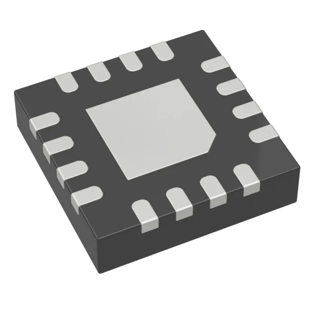
The MAX5477ETE+T packs two independent digital potentiometers in a single 16-TQFN package. Each channel is a 10kΩ resistor string with 256 wiper positions, giving you about 39 Ω per step. The linear taper means the wiper resistance changes uniformly with the digital code — no log scaling, so the firmware math is straight-line interpolation. Both pots share the I²C interface, and the selectable address feature lets you put two of these on the same bus without address conflicts. That covers a four-channel trim/calibration block with one bus master and two ICs.
Non-volatile wiper retention and thermal drift budget
The wiper setting is stored in non-volatile memory — the pot powers up at the last programmed position, not mid-scale. For a bias voltage or threshold trim that must survive a power cycle, this saves a firmware restore routine. Temperature coefficient is 70 ppm/°C typical. Wiper resistance is 325 Ω typical. At the low end of the pot (code 0), the wiper adds this fixed series resistance. In a voltage divider, the output at zero code is not 0 V but a voltage divider between the wiper resistance and the load. Budget it into the transfer function if the application uses the bottom of the range.
Package, supply, and board-fit notes
The 0.5 mm pitch demands a via-in-pad or a tight via ring under the package; a two-layer board can work if the ground plane is on layer 2 and the vias are tented on the bottom side. The digital I²C pins are referenced to VDD — if the bus master runs at 3.3 V and the pot at 5 V, the logic levels are compatible, but the SDA/SCL pull-up resistors must be sized for the higher VDD. No level translator needed. Surface-mount package, supplied in tape and reel or cut tape. The ±25% tolerance on the end-to-end resistance means two channels on the same die can differ by up to 2.5 kΩ — for ratiometric applications this is fine, but for absolute resistance matching, plan for the spread.