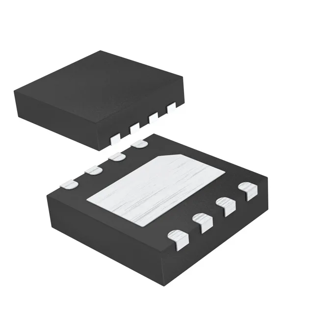
Linear taper, 256 taps, 200kΩ — what the ratings mean for your trim loop
The MAX5419LETA+T is a single-channel, 256-tap digital potentiometer with a linear taper and 200kΩ end-to-end resistance. Linear taper means the resistance between the wiper and either terminal changes in equal steps per tap — 200kΩ / 256 = ~781 Ω per step. The 256-step resolution gives you 0.39% of full scale per step, which is fine for most calibration loops but not for precision audio where 1024-step parts exist. The ±25% absolute tolerance on the end-to-end resistance means a 200kΩ part could measure anywhere from 150kΩ to 250kΩ. That sounds wide, but the ratiometric accuracy — the relative position of each tap — is much tighter. If you are using the pot as a voltage divider (the common case), the absolute value cancels out and only the tap ratio matters. The 35 ppm/°C temperature coefficient adds about 7 Ω/°C drift on the 200kΩ scale, negligible for trimming.
I²C interface with selectable address — bus topology note
Communication is over the I²C bus, two wires (SCL, SDA) plus the supply and ground. The selectable address pin lets you set the device's I²C address to one of two values by tying A0 high or low, so you can put two MAX5419s on the same bus. If you need more channels, the MAX5420 is the dual version (two pots in one package) with the same pinout and interface. The non-volatile memory stores the wiper position in EEPROM — the part powers up at the last programmed setting, not at mid-scale. That matters if the pot sets a bias voltage that must be valid before the microcontroller boots. The write cycle to non-volatile memory takes a few milliseconds; the volatile register updates in microseconds for real-time adjustments.
Package, supply, and temperature — board-fit checklist
The wiper resistance is 325Ω typical — at the bottom of the range, the wiper adds a series resistance that limits the minimum output impedance; for a 200kΩ pot feeding a 10 MΩ op-amp input, the 325Ω is negligible.