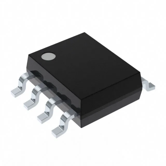
Analog Devices MAX517ACSA+ — DC-DC Power Modules

MAX517ACSA+ 8-Bit DAC, I²C, 6µs, 8-SOIC

MPNMAX517ACSA+
End of Life

Analog Devices MAX517ACSA+ 8-bit voltage-output DAC, I²C serial interface, 6µs settling time, ±1 LSB INL/DNL, 8-SOIC package, 0°C to 70°C.

$10.79Ref. price · indicative, final on quote
Packaging8-SOIC (0.154", 3.90mm Width)
StockContact for availability
Lead timeIn Stock wk
MOQ1 pcs
  • 100% new & originalTraceable channels only — no refurbs, no pulls, no remarked parts.
  • Date & lot codes on quoteStated per line before you commit; label photos on request.
  • MSL-compliant ESD packingMoisture-sealed bags with indicator cards; reels photo-verified.
  • PayPal buyer protectionPay by T/T, PayPal or Payoneer — card payments covered end to end.

Specifications

MAX517ACSA+ Technical Specifications
ParameterValue
Output typeVoltage - Buffered
Mounting typeSurface Mount
Reference typeExternal
Voltage - supply, analog5V
Voltage - supply, digital5V
InterfaceI²C
Operating temperature0°C ~ 70°C
PackageTube
ArchitectureR-2R
INL (DNL)±1 (Max), ±1 (Max)
Settling time6µs (Typ)
Number of bits8
Case8-SOIC (0.154\", 3.90mm Width)
Differential outputNo
Number of d (A converters)1

Product details

8-bit resolution with a 6 µs update window

The MAX517ACSA+ is an 8-bit digital-to-analog converter with a voltage-buffered output, meaning the DAC can source current directly into a load without an external buffer amplifier. The 6 µs typical settling time sets the maximum update rate — for a closed-loop control system updating at 100 kHz, the DAC output has settled to within 1 LSB before the next conversion starts. Single-supply operation at 5 V for both analog and digital rails simplifies the power tree — no separate AVDD and DVDD supplies are needed. The external reference input allows the full-scale output voltage to be set by the system designer, decoupling the DAC range from the supply rail.

I²C bus integration and linearity

Data transfer uses the I²C serial interface, which requires only two bus lines (SCL, SDA) and supports standard-mode (100 kHz) and fast-mode (400 kHz) clock rates. The 8-bit data word maps to 256 output levels; the ±1 LSB max INL and ±1 LSB max DNL guarantee monotonicity across the full code range — no missing codes at the transition points. The R-2R resistor-ladder architecture keeps the die small and the power consumption low, but the output impedance is code-dependent — the buffered output stage isolates the ladder from the load, so the external impedance does not affect linearity.

Frequently asked questions

What is the settling time and why does it matter?

The typical settling time is 6 µs to within 1 LSB for a full-scale step. This determines how fast the DAC output can be updated — at 6 µs the maximum update rate is about 166 kHz, though the I²C bus transfer time adds overhead.

What is the output type and do I need an external buffer?

The output is voltage-buffered, so the DAC can drive a resistive or capacitive load directly without an external op-amp. The buffer's output impedance is low, maintaining linearity across the load range.