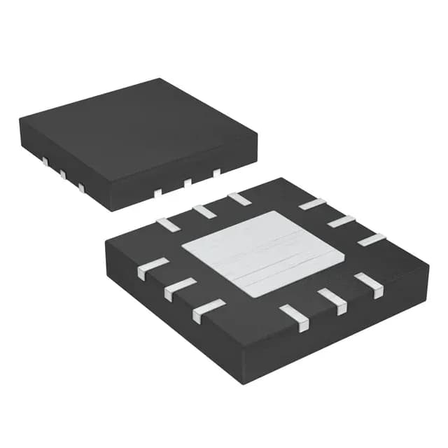
Analog Devices MAX5064BATC+T — DC-DC Power Modules

MAX5064BATC+T Half-Bridge Gate Driver, 2A Peak

MPNMAX5064BATC+T
End of Life

Analog Devices MAX5064BATC+T, half-bridge gate driver, N-Channel MOSFET, 2 independent channels, 2A peak source/sink, 8V~12.6V supply, 125V bootstrap, inverting/non-inverting inputs, 12-WQFN Exposed Pad, -40°C to 150°C.

$4.07Ref. price · indicative, final on quote
Packaging12-WQFN Exposed Pad
StockContact for availability
MOQ1 pcs
  • 100% new & originalTraceable channels only — no refurbs, no pulls, no remarked parts.
  • Date & lot codes on quoteStated per line before you commit; label photos on request.
  • MSL-compliant ESD packingMoisture-sealed bags with indicator cards; reels photo-verified.
  • PayPal buyer protectionPay by T/T, PayPal or Payoneer — card payments covered end to end.

Specifications

MAX5064BATC+T Technical Specifications
ParameterValue
Gate typeN-Channel MOSFET
Input typeInverting, Non-Inverting
Channel typeIndependent
Mounting typeSurface Mount
Voltage8V ~ 12.6V
Logic voltage - VIL, VIH0.8V, 2V
High side voltage - max (Bootstrap)125 V
Current - peak output (Source, sink)2A, 2A
Operating temperature-40°C ~ 150°C (TJ)
PackageTape & Reel (TR); Cut Tape (CT)
Case12-WQFN Exposed Pad
Number of drivers2
Driven configurationHalf-Bridge
Rise (Fall time)65ns, 65ns

Product details

Half-bridge driver with 2A peak gate drive — what it does

The MAX5064BATC+T is a half-bridge gate driver from Analog Devices (formerly Maxim Integrated) designed to drive two N-channel MOSFETs in a half-bridge configuration. It delivers 2A peak source and 2A peak sink current, which gives you the muscle to charge and discharge large gate capacitances quickly — useful for keeping switching losses low in DC-DC converters, motor-drive inverters, and synchronous rectifier stages. The bootstrap supply is rated to 125 V, so it handles 48 V and 72 V bus rails with margin, and the independent inverting and non-inverting input channels let you wire the dead-time logic however your controller expects it.

125 V bootstrap — what that means for your bus voltage

The 125 V maximum high-side voltage (bootstrap) sets the absolute ceiling for the floating supply that powers the high-side driver. If your half-bridge DC bus sits at 48 V or even 72 V nominal, you have healthy headroom. The 8 V to 12.6 V supply range on the low side is typical for biasing the driver core and gate-drive rails; stay inside that window or the UVLO may not release cleanly.

Temperature range and package — where it fits

Rated for -40°C to 150°C junction temperature, so this driver is comfortable in under-hood automotive, industrial motor drives, and outdoor telecom equipment where ambient heat is a given. The 12-WQFN with exposed pad (4x4 mm) needs a thermal via array under the paddle to pull heat into the PCB ground plane — without it, the junction temp rises fast when you push 2 A gate-drive pulses at high frequency.

Lifecycle and sourcing

Marked as Active in the product lifecycle, so no LTB risk for new designs. ROHS3 compliant. No pin-compatible second source is listed in the official cross-reference, so you are single-sourced on the die — plan your buffer stock accordingly.

Frequently asked questions

What is the peak output current of MAX5064BATC+T?

The driver sources and sinks 2A peak. This is the figure to use when sizing the gate resistor and estimating switching times for your MOSFETs — it is fast enough for most hard-switched converters up to a few hundred kilohertz.

What supply voltage does MAX5064BATC+T need?

The low-side supply range is 8 V to 12.6 V. The high-side bootstrap is rated to 125 V maximum. Running the low-side rail below 8 V risks UVLO dropout.

What package does MAX5064BATC+T come in?

12-WQFN with exposed pad, also designated as 12-TQFN (4x4 mm). The exposed pad must be soldered to a thermal land on the PCB.