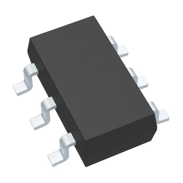
Analog Devices MAX5048CAUT+T — DC-DC Power Modules

MAX5048CAUT+T Low-Side Gate Driver, 3A/7A Peak, SOT-23-6

MPNMAX5048CAUT+T
End of Life

Maxim MAX5048CAUT+T, Low-Side Gate Driver IC, Single N-Channel MOSFET, 3A Source / 7A Sink Peak Output, 28ns/13ns Rise/Fall, Inverting/Non-Inverting Input, 4V to 14V Supply, SOT-23-6, -40°C to 150°C.

$1.82Ref. price · indicative, final on quote
PackagingSOT-23-6
StockContact for availability
MOQ1 pcs
  • 100% new & originalTraceable channels only — no refurbs, no pulls, no remarked parts.
  • Date & lot codes on quoteStated per line before you commit; label photos on request.
  • MSL-compliant ESD packingMoisture-sealed bags with indicator cards; reels photo-verified.
  • PayPal buyer protectionPay by T/T, PayPal or Payoneer — card payments covered end to end.

Specifications

MAX5048CAUT+T Technical Specifications
ParameterValue
Gate typeN-Channel MOSFET
Input typeInverting, Non-Inverting
Channel typeSingle
Mounting typeSurface Mount
Voltage4V ~ 14V
Logic voltage - VIL, VIH0.8V, 2V
Current - peak output (Source, sink)3A, 7A
Operating temperature-40°C ~ 150°C (TJ)
PackageTape & Reel (TR); Cut Tape (CT)
CaseSOT-23-6
Number of drivers1
Driven configurationLow-Side
Rise (Fall time)28ns, 13ns

Product details

Low-side gate driver for N-channel MOSFETs

The Maxim MAX5048CAUT+T is a single-channel, low-side gate driver for N-channel MOSFETs. Peak output current is 3A source and 7A sink, with rise and fall times of 28ns and 13ns.

Peak current and switching speed — what they mean for your design

The 3A source / 7A sink peak current rating is the key parameter for driving the gate capacitance of a power MOSFET. A higher sink current (7A) means faster turn-off, reducing switching losses and cross-conduction in half-bridge topologies. The 28ns rise and 13ns fall times are typical at a given load capacitance — expect these to scale with the total gate charge of the MOSFET you select. If you are driving a large IGBT or paralleled MOSFETs, verify the driver's peak current against the gate charge curve, not just the headline number.

Package and thermal considerations

The SOT-23-6 package is compact, but its thermal dissipation is limited. The driver is rated for continuous operation up to 150°C junction temperature, but at high switching frequencies or with large gate charge loads, the package may overheat. Ensure adequate PCB copper area for heat sinking, and consider the total power dissipation from gate drive losses (Qg × Vdd × fsw). For high-frequency or high-current applications, a driver in a larger package (e.g., SOIC-8) may be necessary.

Lifecycle and sourcing

It is ROHS3 compliant.

Frequently asked questions

Is MAX5048CAUT+T compatible with 3.3V logic?

Yes. The logic input thresholds (VIL = 0.8V, VIH = 2V) are compatible with 3.3V logic outputs. However, the driver supply voltage must be at least 4V, so a separate gate drive rail is needed if the system only has 3.3V.