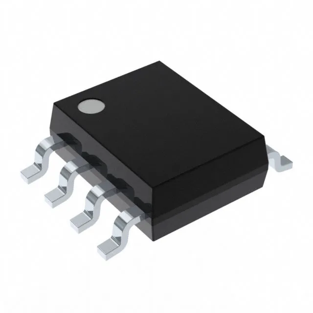
76 V input buck in an 8-SOIC
The MAX5033AASA+T is a fixed 3.3 V output step-down (buck) regulator from Analog Devices, rated for 500 mA continuous output current. Its input range spans 7.5 V to 76 V, which means it can regulate down from a 48 V telecom rail, a 24 V industrial bus, or a 12 V automotive supply without needing a separate pre-regulator.
What the headline ratings mean for the BOM
The 500 mA output current is continuous and derated with temperature; at 125°C junction, the available current drops, so the thermal design must keep the die below that limit at full load. The fixed 3.3 V output removes the need for an external feedback divider, saving two resistors and one feedback-node bypass capacitor from the BOM. Switching at 125 kHz, the regulator uses an external diode (no synchronous rectifier) and an inductor sized for the ripple current at that frequency. The lower switching frequency means larger magnetics than a 500 kHz part, but it also reduces switching losses and makes the layout less sensitive to parasitic inductance in the switch node. The 76 V maximum input covers the full range of a 48 V nominal telecom bus (which can hit 60 V on a ring-trip or 72 V during a lightning surge) without an external clamp. The 7.5 V minimum input means the regulator starts up cleanly from a 12 V rail that dips during cranking, as long as the bulk capacitor holds the input above 7.5 V.
The 8-SOIC footprint is standard and the thermal pad is the die attach paddle on the bottom of the package; the copper area on the PCB under the part sets the junction-to-ambient thermal resistance. Available in Tape & Reel (TR) or Cut Tape (CT) for prototyping.