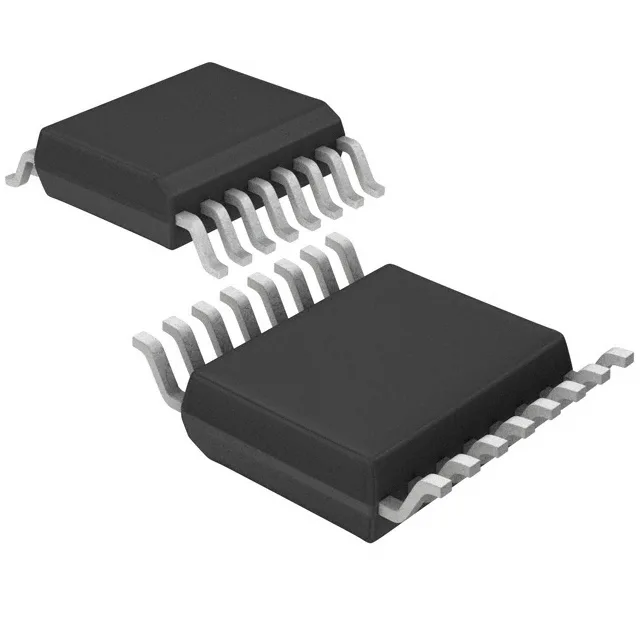
On-resistance and signal-integrity parametrics
The MAX4690EAE+: 1.25 Ohm max on-resistance with 90 mOhm channel-to-channel matching (ΔRon) means the voltage drop across the switch is consistent between the two SPST-NO circuits. For a 10 mA signal current, the drop is under 12.5 mV — negligible in a precision analog path, but the matching figure tells you the two channels track within 0.09 Ohm, which matters when the switch is used in a differential or gain-scaling application where channel imbalance would introduce offset error. Switching speed is 275 ns max turn-on, 175 ns max turn-off. In a multiplexed data-acquisition system sampling at 1 MHz, the on-time window is about 1 µs — the 275 ns settling eats 27.5% of the aperture, so the downstream ADC must wait for the switch to settle before converting. The 175 ns turn-off ensures the channel clears before the next sample, preventing channel bleed. Crosstalk is specified at -65 dB at 1 MHz. In a 2-channel multiplexer switching a 1 Vpp signal, -65 dB means the unwanted signal coupled from the off channel is about 560 µV at the on-channel output — below the LSB of a 12-bit ADC with a 2.5 V reference, but visible to a 16-bit converter. This spec is measured at 1 MHz; crosstalk typically improves at lower frequencies and degrades above 1 MHz due to parasitic capacitance in the 16-SSOP package. Charge injection is 550 pC typical. When the switch opens, this charge is dumped onto the load capacitance — into a 100 pF load it creates a 5.5 V glitch. In a sample-and-hold front end, this glitch must settle before the ADC conversion starts. The 115 pF channel capacitance (CS(off), CD(off)) contributes to the RC time constant of the off-isolation path; higher capacitance increases feedthrough at high frequencies. Leakage current is 500 pA max per channel in the off state. In a high-impedance sensor interface where the source impedance is 10 MOhm, 500 pA leakage creates a 5 mV offset — acceptable for 12-bit but marginal for 16-bit without calibration.
Supply flexibility and dual-rail operation
This covers the common analog rails: single +5 V, +12 V, +15 V, +24 V, and dual ±5 V, ±12 V, ±15 V. In a ±15 V system the switch handles bipolar signals up to the rail, and the 1.25 Ohm on-resistance stays flat across the signal swing because the internal charge pump keeps the gate drive constant. The SPST-NO (single-pole single-throw, normally-open) topology with a 1:1 multiplexer/demultiplexer circuit means each of the two channels is a simple on/off pass gate. No break-before-make or make-before-break timing is built in — if the application requires channel sequencing during switching, external logic or a timing delay must manage the overlap.
Package, compliance, and procurement posture
The MAX4690EAE+ ships in a Tube (the standard 16-SSOP tube, typically 50 or 100 pieces per tube depending on the manufacturer's packing standard). ROHS3 compliant per the manufacturer's declaration — no exemptions for lead in solder or PBB/PBDE flame retardants. This covers EU RoHS Directive 2011/65/EU and its amendment 2015/863.