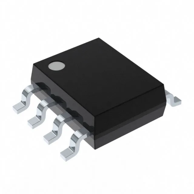
Package and board-fit for the 8-SOIC footprint
The MAX4544ESA+: Surface mount mounting means the part reflows on the same footprint as any generic SOIC-8; the narrow body (3.90 mm wide) fits a tight analog channel without consuming extra board area. A single SPDT switch circuit in this package means one signal path per device — plan one part per switched line, not a mux bank.
What the key analog specs mean for signal integrity
On-state resistance of 60 Ohm max is moderate — for a 10 kOhm load the voltage divider loss is under 0.6%, but driving a 50 Ohm terminated line would attenuate the signal by more than half. The 800 mOhm channel-to-channel matching keeps the resistance difference between the two throws tight, which matters for differential or matched-gain paths where any imbalance adds offset. Charge injection of 1 pC means each time the switch toggles, a 1 pC charge packet dumps onto the signal node — on a 10 pF sampling capacitor that creates a 100 mV glitch. For precision ADC front-ends or sample-and-hold circuits, budget settling time after switching or use a downstream track-and-hold. Leakage current of 100 pA max sets the floor for high-impedance nodes: a 1 MOhm source sees a 100 µV offset from leakage, negligible for 12-bit but visible at 16-bit and above. Crosstalk of -90 dB at 1 MHz means the off-channel isolation is about 31.6 µV per volt of aggressor signal at 1 MHz — good enough for audio or low-frequency analog multiplexing, but at 10 MHz the isolation degrades due to parasitic capacitance through the package. Channel capacitance of 8 pF on both source and drain adds to the node capacitance; in a high-impedance path this limits bandwidth — a 10 kOhm source driving 8 pF gives a 2 MHz corner. Switching times of 100 ns (Ton) and 75 ns (Toff) max define the minimum pulse width the switch can pass cleanly — at 100 ns, the effective bandwidth is about 3.5 MHz for a sine wave, so multiplexing a 1 MHz analog signal is fine, but a 10 MHz video signal would suffer amplitude loss and phase shift.