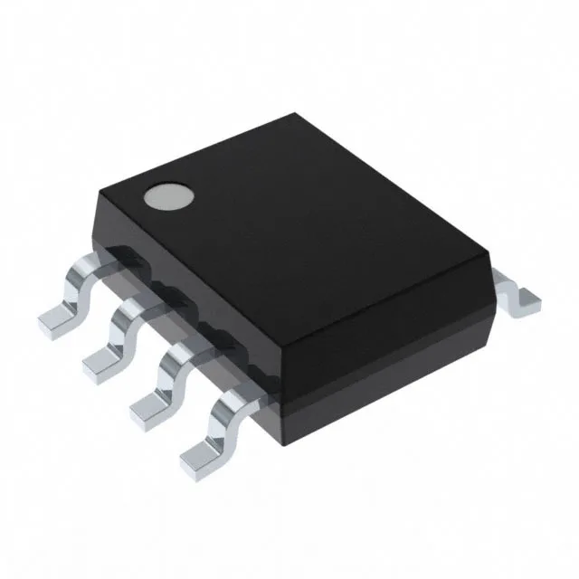
Dual SPDT switch in an 8-SOIC — what the key ratings mean for your signal path
The MAX4528CSA+: Each of the two switch sections implements a 2:1 multiplexer/demultiplexer topology, so a single IC can route two independent signals between one common and two selectable terminals. On-resistance is specified at 110 Ohm max, with channel-to-channel matching held to 3 Ohm. For a precision analog front-end, the matching figure matters more than the absolute R_on — it tells you the gain error introduced by switching between channels will track within 3 Ohm, which keeps the voltage-divider ratio predictable across the two signal paths. Charge injection is rated at 1 pC typical. In a sample-and-hold or integrator circuit, this is the amount of charge dumped onto the hold capacitor when the switch turns off. A 1 pC injection into a 10 nF cap produces a 100 µV glitch — low enough for 12-bit systems without external compensation. Leakage current is 500 pA max off-channel, and channel capacitance (CS(off), CD(off)) is 13 pF. Together these set the off-isolation floor at high frequencies and the settling time when switching into a high-impedance load.
Supply rails and temperature grade — where this part fits on the board
The switch operates from a single supply of 2.7 V to 12 V, or from dual supplies of ±2.7 V to ±6 V. Dual-supply operation lets the switch pass bipolar signals without a DC bias — the signal swing can go negative relative to the system ground, which is useful for audio paths or bipolar sensor outputs. This limits deployment to indoor, temperature-controlled environments — office equipment, bench instrumentation, or telecom racks where ambient stays within that band.