What the 100 Ohm on-resistance means for your signal path
The MAX4519ESD+: The 100 Ohm max on-resistance sets the insertion loss floor for the analog path. In a 50-Ohm system, the switch adds roughly 2 dB of loss; in a high-impedance sensor front-end the voltage divider effect is negligible. The 4 Ohm max channel-to-channel matching (ΔRon) keeps gain error uniform across both channels — useful when the two DPST sections are part of a differential or matched-gain stage.
Switching speed and charge injection — the sample-hold trade-off
150 ns max turn-on and turn-off time sets the multiplexer's throughput ceiling. For a data-acquisition system scanning two channels, the aggregate sample rate is limited by the sum of switch settling plus ADC acquisition time.
Crosstalk and leakage — isolation in a mixed-signal board
-92 dB crosstalk at 100 kHz means the two DPST channels are isolated well enough to prevent signal bleed-through in precision analog multiplexing. The 100 pA max off-leakage (IS(off)) adds a DC error that, at 25°C, is negligible even with a 1 MOhm source impedance (100 µV offset). The channel capacitance — 5 pF source-off, 10 pF drain-off — loads the upstream driver and sets the bandwidth roll-off when the switch is off.
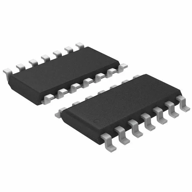
The 14-SOIC narrow-body package (3.90 mm width) is a standard JEDEC footprint. The surface-mount assembly profile matches the typical 260°C peak reflow for lead-free solder. The tube shipping format is common for small-quantity prototyping and low-volume production — no reel tape-up needed for hand-assembly or rework.
Compliance and documentation
The MAX4519ESD+ is ROHS3 compliant — no RoHS exemptions for lead in solder or any of the six restricted substances above the threshold. Analog Devices provides the standard datasheet, which includes the full electrical table, package drawing, and application notes for charge-injection compensation and crosstalk mitigation.