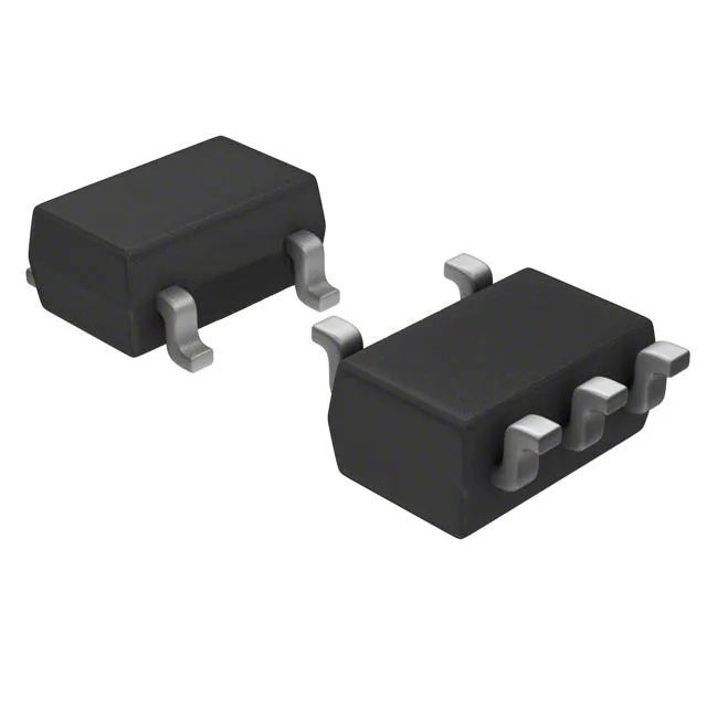
SOT-23-5 footprint and supply range
The MAX4514CUK+T is a single-pole single-throw normally-open analog switch in a 5-lead SOT-23-5 package (SC-74A). The 0.95 mm pitch and 2.9 mm body length fit tight analog front-end layouts where board area is the constraint.
On-resistance and switching speed
20 Ohm max on-resistance at 25 °C keeps the insertion loss below 0.5 dB into a 10 kOhm load — the flatness across the analog signal range is typically 5 Ohm, so the gain error in a precision attenuator stays under 0.05 %. 150 ns turn-on and 100 ns turn-off max allow the switch to gate audio sample rates up to several megahertz without introducing audible pop or timing skew in multiplexed data acquisition. Charge injection is 2 pC typical — for a 10 pF hold capacitor on a sample-and-hold front end, the injected charge produces a 200 mV step, which must be accounted for in the acquisition settling budget.
Leakage and capacitance floor
1 nA max off-leakage at 25 °C means the switch does not load the signal source — in a 10 MOhm source impedance circuit the voltage error from leakage is 10 mV, negligible for 12-bit systems. 14 pF channel capacitance on both source and drain pins sets the bandwidth ceiling — into a 50 Ohm load the -3 dB point is roughly 225 MHz, well above the audio and low-frequency instrumentation band.