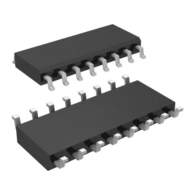
Dual SP4T in 16-SOIC — two independent 4:1 multiplexers
The MAX399ESE+ packs two SP4T (single-pole, 4-throw) switches into a single 16-SOIC package, each circuit implementing a 4:1 multiplexer/demultiplexer. Two independent signal paths share the same supply rails but switch independently, so a single IC handles dual-channel analog routing — four inputs per channel, one output per channel — without an external mux cascade.
100 Ohm on-resistance with 6 Ohm channel matching
On-state resistance is 100 Ohm max, with channel-to-channel matching held to 6 Ohm max. For a 10 kOhm source impedance, the 100 Ohm Ron adds 1 % insertion loss — negligible in most signal chains — but the matching figure matters when you need consistent attenuation across channels in a multiplexed measurement system. The 2 pC charge injection means each channel switch injects a 2 pC glitch into the signal path; in a sample-and-hold front-end this glitch must settle before the ADC conversion window opens.
-92 dB crosstalk at 100 kHz — isolation for mixed-signal boards
Channel-to-channel crosstalk is -92 dB at 100 kHz. This is the isolation floor between the two SP4T circuits on the same die — a 100 kHz signal on one channel leaks into the adjacent channel at 92 dB below the carrier. For a 16-bit ADC with a 96 dB SNR budget, this crosstalk stays below the noise floor, so the mux does not limit the system's dynamic range in multiplexed data acquisition.
Supply flexibility: 3-15 V single or ±3-8 V dual
The switch operates from a single supply of 3 V to 15 V, or from dual supplies of ±3 V to ±8 V. Single-supply mode passes signals from ground to V+; dual-supply mode passes bipolar signals symmetric around ground. The 150 ns max turn-on and turn-off times set the switching speed ceiling — at 150 ns, the mux can switch channels at roughly 3.3 MHz without the output settling time dominating the acquisition window.
Package and board-fit: 16-SOIC, Tube
The 1.27 mm pitch fans out easily on a two-layer board — no via-in-pad required. Surface-mount assembly with standard reflow profile; the -40 to 85 °C operating range means the part survives wave-solder secondary-side processing if the board goes through a second pass.