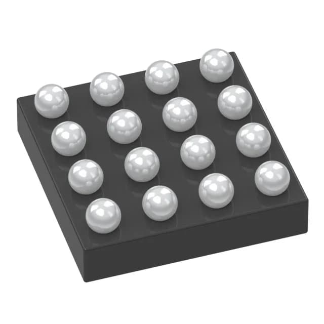
Analog Devices MAX32660GWE+T — Analog & Data Acquisition

MAX32660GWE+T ARM Cortex-M4F MCU, 96MHz, 256KB Flash

MPNMAX32660GWE+T
End of Life

Maxim Integrated DARWIN series MAX32660GWE+T, ARM Cortex-M4F 32-bit MCU, 96MHz, 256KB Flash, 96K x 8 RAM, 14 I/O, I²C/SPI/UART, -40°C to 105°C, 16-WLP (1.55x1.57 mm), Tape & Reel.

$3.05Ref. price · indicative, final on quote
Packaging16-WFBGA, WLBGA
StockContact for availability
MOQ1 pcs
  • 100% new & originalTraceable channels only — no refurbs, no pulls, no remarked parts.
  • Date & lot codes on quoteStated per line before you commit; label photos on request.
  • MSL-compliant ESD packingMoisture-sealed bags with indicator cards; reels photo-verified.
  • PayPal buyer protectionPay by T/T, PayPal or Payoneer — card payments covered end to end.

Specifications

MAX32660GWE+T Technical Specifications
ParameterValue
SeriesDARWIN
Mounting typeSurface Mount
Oscillator typeInternal
Program memory typeFLASH
Voltage - supply (Vcc (Vdd))1.71V ~ 3.63V
Operating temperature-40°C ~ 105°C (TA)
Speed96MHz
PackageTape & Reel (TR); Cut Tape (CT)
RAM size96K x 8
Core size32-Bit Single-Core
PeripheralsBrown-out Detect/Reset, DMA, I²S, POR, PWM, WDT
ConnectivityI²C, SPI, UART/USART
Number of i (O)14
Core processorARM® Cortex®-M4F
Case16-WFBGA, WLBGA
Program memory size256KB (256K x 8)

Product details

What this MCU is and where it fits

The Maxim Integrated MAX32660GWE+T is a 32-bit ARM Cortex-M4F microcontroller from the DARWIN series, clocked at 96 MHz with a hardware floating-point unit. It packs 256 KB of Flash and 96 KB of SRAM into a 16-pin wafer-level package (WLP) measuring 1.55 x 1.57 mm — roughly the footprint of a grain of rice. This is the part you reach for when a sensor node, wearable, or portable instrument needs real DSP or control-loop math in a board-area-constrained design.

96 MHz Cortex-M4F — what the speed buys you

96 MHz on a Cortex-M4F with single-cycle MAC and FPU means you can run a 3rd-order IIR filter or a PID loop with floating-point coefficients without bit-shifting or lookup tables. The 14 available I/O lines limit peripheral muxing, but the internal oscillator and the set of I²C, SPI, and UART/USART interfaces cover most sensor-bridge and actuator-control scenarios. Brown-out detect, POR, and a watchdog timer are on-chip, so you can skip external supervisors in many designs.

Temperature grade and deployment environment

Rated for -40°C to 105°C ambient, this MCU operates from a 1.71 V to 3.63 V supply.

Package reality: 16-WLP assembly considerations

The 16-WLP (1.55 x 1.57 mm) is a wafer-level chip-scale package with solder balls on the bottom — no leads, no plastic overmold. That means the PCB land pattern must match the ball pitch exactly, and reflow profile needs to follow the JEDEC standard for WLP. No lab, no bench: if you are swapping this on site, you will need a hot-air rework station with a fine nozzle and a steady hand.

Lifecycle and sourcing posture

The MAX32660GWE+T carries an Active lifecycle status and is ROHS3 compliant.

Frequently asked questions

What are the pin details and package for MAX32660GWE+T?

The MAX32660GWE+T is supplied in a 16-WLP (wafer-level package) with a body size of 1.55 x 1.57 mm. The package has 14 general-purpose I/O pins plus power and ground. Pin assignments are documented in the device datasheet; the WLP ball map is critical for PCB layout.

How to program MAX32660GWE+T?

The MAX32660GWE+T is programmed via its serial wire debug (SWD) interface, using standard ARM development tools. Maxim provides a DARWIN-series SDK and example code. The internal oscillator eliminates the need for an external clock source during programming.