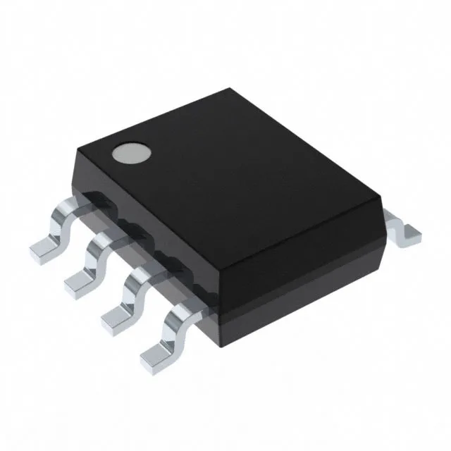
Dual SPST analog switch with 60 Ohm on-resistance
The MAX323ESA+ from Analog Devices integrates two independent SPST-NO (single-pole, single-throw, normally-open) analog switches in an 8-SOIC package. Each switch presents a maximum on-resistance of 60 Ohm, with channel-to-channel matching held to 800 mOhm — the resistance mismatch between the two channels stays under one ohm, which matters when the switch pair carries a differential signal where gain symmetry is required.
Supply range and signal handling
The 1:1 multiplexer/demultiplexer circuit means each switch is a straight pass-gate — no internal routing logic, just the FET channel between the source and drain terminals. Switching times are 150 ns max for turn-on (Ton) and 100 ns max for turn-off (Toff). In a multiplexed data-acquisition front-end sampling at 500 kSPS, the 150 ns settling window after the switch closes must be budgeted before the ADC conversion starts — the switch itself does not limit the throughput, but the downstream settling does. Charge injection is 1 pC typical. When the switch opens, this charge packet couples onto the hold capacitor of a downstream sample-and-hold — 1 pC into a 10 pF cap produces a 100 mV glitch, so the cap value and the acquisition time after the switch opens must be sized to absorb the injected charge before the ADC samples.
Crosstalk and leakage in precision analog paths
Crosstalk between channels is rated at -85 dB at 1 MHz. In a dual-channel multiplexer switching audio or low-frequency sensor signals, this isolation means the closed channel sees less than 0.006 % of the signal from the open channel at 1 MHz — the coupling capacitance through the substrate and package is the dominant path, and the -85 dB figure confirms the die layout and pinout keep the channels electrically separate. Off-state leakage current is 100 pA maximum. In a high-impedance node such as a photodiode amplifier input, 100 pA of leakage from the open switch adds to the sensor's dark current — for a 10 pA photodiode, the switch leakage doubles the baseline offset and must be calibrated out or trimmed at the system level. Channel capacitance is 9 pF for both the source and drain terminals when the switch is off. This capacitance loads the signal line and sets the bandwidth of the off-channel — a 9 pF cap in parallel with a 10 kOhm source impedance creates a 1.8 MHz low-pass pole, which is acceptable for most audio and instrumentation signals but limits RF or video paths.
Package, temperature grade, and compliance
The supplier device package is 8-SOIC, surface-mount, with a tube shipping medium.