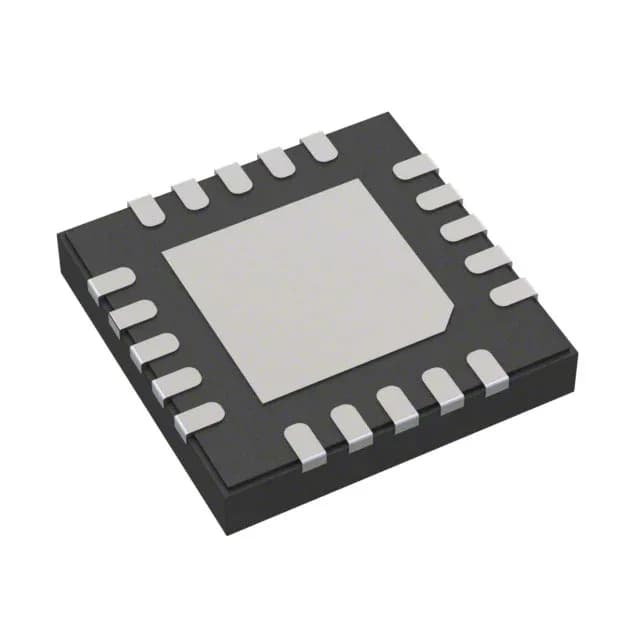
Analog Devices MAX20040BATPA/VY+ — Discrete Semiconductors

MAX20040BATPA/VY+ buck-boost regulator, AEC-Q100, 1.2 A

MPNMAX20040BATPA/VY+
End of Life

Maxim Integrated MAX20040BATPA/VY+, Automotive AEC-Q100, Step-Up/Step-Down (Buck-Boost) Regulator, 1 Output, 1.2 A, 2.2 MHz, Programmable Output, 20-TQFN-EP (4x4), -40°C to 125°C.

$5.78Ref. price · indicative, final on quote
Packaging20-WFQFN Exposed Pad
StockContact for availability
MOQ1 pcs
  • 100% new & originalTraceable channels only — no refurbs, no pulls, no remarked parts.
  • Date & lot codes on quoteStated per line before you commit; label photos on request.
  • MSL-compliant ESD packingMoisture-sealed bags with indicator cards; reels photo-verified.
  • PayPal buyer protectionPay by T/T, PayPal or Payoneer — card payments covered end to end.

Specifications

MAX20040BATPA/VY+ Technical Specifications
ParameterValue
SeriesAutomotive, AEC-Q100
Output typeProgrammable (Fixed)
Mounting typeSurface Mount, Wettable Flank
Voltage - input36V
Voltage - output15V
Current - output1.2A
Frequency2.2MHz
Number of outputs1
Operating temperature-40°C ~ 125°C
PackageTray
FunctionStep-Up/Step-Down
TopologyBuck-Boost
Case20-WFQFN Exposed Pad
Output configurationPositive
Synchronous rectifierYes

Product details

Buck-boost regulator for automotive power rails

The MAX20040BATPA/VY+ from Maxim Integrated is a single-output buck-boost switching regulator rated for automotive environments. It accepts a 2 V to 36 V input range and delivers a programmable output up to 15 V at 1.2 A, switching at 2.2 MHz. The buck-boost topology keeps the output regulated whether the input sits below, at, or above the output voltage — a requirement for automotive battery rails that swing during cold-crank, start-stop, and load-dump transients. The part is AEC-Q100 qualified and operates from -40°C to 125°C, placing it in the under-hood or engine-bay tier, not just cabin electronics. The package includes an exposed pad for thermal dissipation and wettable flanks on the QFN pads, which lets automated optical inspection (AOI) verify solder-joint quality on the production line.

2.2 MHz switching — small inductor, tight layout

At 2.2 MHz, the switching frequency pushes the inductor and output capacitor values down, shrinking the total power-stage footprint for space-constrained ECU layouts. The trade-off is that the switching edges couple into the PCB more easily — plan a solid ground plane under the IC and keep the switching node loop short. The synchronous rectifier (integrated) improves efficiency and removes the external Schottky diode, saving one component and one placement step.

Output programming — resistor divider sets the voltage

The output voltage is programmable via an external resistor divider, with a range up to 15 V. The fixed-programmable designation means the internal reference is fixed, but the feedback pin accepts the divider ratio to set the output.

Lifecycle and sourcing

The MAX20040BATPA/VY+ carries an Active lifecycle status and is ROHS3 compliant. It is not in a last-time-buy or phase-out window. For production programs that need a qualified second source, no pin-compatible alternate is listed on the official cross-reference — the part is sole-sourced to Maxim's automotive line.

Frequently asked questions

What is the lead time for MAX20040BATPA/VY+?

Lead time is confirmed at quote time against an RFQ. It varies with quantity and current factory allocation; request a quote for the specific delivery window your BOM requires.

Is MAX20040BATPA/VY+ compatible with 3.3V output?

Yes, the output is programmable via a resistor divider. With the proper feedback network, the regulator can be set to 3.3 V within its 15 V maximum output range.

Does MAX20040BATPA/VY+ meet automotive AEC-Q100 qualification?

Yes, it is listed under the Automotive, AEC-Q100 series, meaning it has passed the stress tests required for automotive-grade qualification.

How do I program the output voltage of MAX20040BATPA/VY+?

The output voltage is set by an external resistor divider connected to the feedback pin. The datasheet provides the formula to calculate resistor values for the desired output up to 15 V.