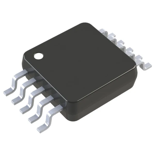
Active production — still a current BOM line
The MAX1954EUB+T: ROHS3 compliant — no lead, mercury, cadmium, or other restricted substances above threshold limits, which simplifies the compliance paperwork for EU and UKCA markets.
300 kHz buck controller — the switching frequency sets the passives
Fixed 300 kHz switching frequency is the design anchor: the inductor value and output capacitor bank are sized around this rate. At 300 kHz, a typical 10 µH inductor and 100 µF ceramic output cap handle most 3.3V and 5V rail conversions without pushing the ripple above 30 mV. The synchronous rectifier replaces the catch diode with a low-Rds(on) internal FET, which lifts efficiency into the mid-90s at full load compared to a diode-based buck. No external Schottky needed — one fewer BOM line and one less thermal spot on the board. 89% maximum duty cycle means the controller can run with the input voltage as low as about 3.4V when regulating a 3.3V output — useful when the input rail sags under load.
Operates from 3V to 5.5V supply — covers the two most common logic rails (3.3V and 5V) without needing an extra regulator. The controller draws its own bias from this rail, not from the output. A base-station power supply or an outdoor sensor node that sees -20°C startup and 70°C continuous operation stays inside the operating envelope without derating.
10-pin µMAX — footprint and placement
Housed in a 10-pin µMAX/uSOP (3.0 mm × 3.0 mm body, 0.50 mm pitch). The small footprint fits on a 2-layer board with the inductor and output caps placed close — the switching loop stays tight, which keeps radiated EMI below the 30 MHz residential limit in most layouts. Surface-mount package with a standard MSL rating — no special bake required before reflow if the sealed bag stays intact. The 0.50 mm pitch is pick-and-place friendly with a 0.30 mm stencil aperture for the thermal pad.