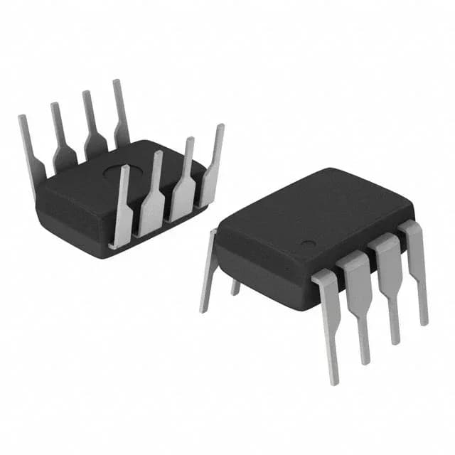
A current-mode controller for boost and buck-boost designs
The Maxim Integrated MAX1771CPA+ is a current-mode PWM controller designed for step-up (boost) and step-up/step-down (buck-boost) topologies. It drives an external N-channel MOSFET via a transistor driver output, operating at a fixed 300 kHz switching frequency. The controller accepts a supply voltage from 3 V to 16.5 V, making it suitable for battery-powered equipment, multi-cell Li-ion packs, and regulated 12 V industrial rails. Maximum duty cycle of 92% provides headroom for high step-up ratios. The part comes in an 8-pin PDIP through-hole package, which is easy to hand-solder and breadboard during prototyping.
300 kHz switching — inductor sizing and EMI
The 300 kHz switching frequency is a middle ground between efficiency and magnetics size. It allows the use of small, low-cost inductors and capacitors while keeping switching losses moderate. At this frequency, the controller does not support clock synchronization (no SYNC pin), so it operates as a standalone regulator; multiple converters must rely on external filtering or beat-frequency mitigation if co-located.
92% duty cycle — what it means for the boost ratio
A 92% maximum duty cycle is the key parameter for boost converter design. It sets the theoretical maximum step-up ratio: Vout ≈ Vin / (1 - D). With D_max = 0.92, the output can be up to 12.5× the input voltage (ignoring diode and switch losses). Practical designs will see lower ratios due to parasitic resistances, but this duty cycle provides generous headroom for generating, say, 12 V from a 3 V input or 24 V from a 5 V rail.
Lifecycle and sourcing reality
The MAX1771CPA+ carries an Active lifecycle status and is ROHS3 compliant. For new designs, the through-hole PDIP package is less common in high-volume SMT builds, but it is widely available through independent distribution and is quoted to order against an RFQ.
Temperature grade — commercial only
Rated for 0°C to 70°C ambient, this part is intended for indoor, temperature-controlled environments such as benchtop instruments, consumer electronics, and office equipment. It is not specified for automotive or industrial extended-temperature applications. If the bill of materials calls for -40°C operation, a different controller with an industrial temperature rating is needed.