Analog Devices MAX17602AUA+ — Discrete Semiconductors

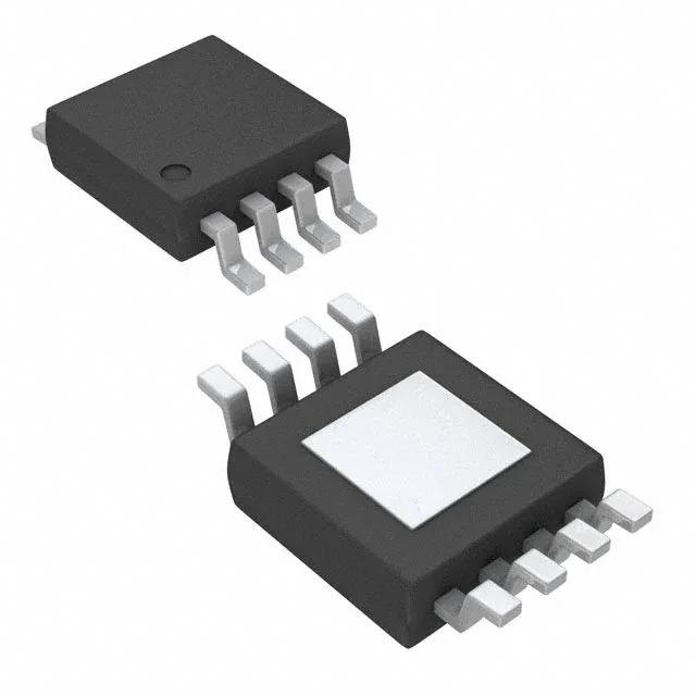
MAX17602AUA+ Low-Side Gate Driver, 4A Peak, 8-uMAX-EP

MPNMAX17602AUA+
End of Life

Analog Devices MAX17602AUA+ low-side gate driver, dual independent channels, 4A peak output, 4V to 14V supply, N-channel MOSFET gate type, 8-uMAX-EP surface-mount package, tube.

$2.47Ref. price · indicative, final on quote
Packaging8-TSSOP, 8-MSOP (0.118", 3.00mm Width) Exposed Pad
StockContact for availability
Lead timeIn Stock wk
MOQ1 pcs
  • 100% new & originalTraceable channels only — no refurbs, no pulls, no remarked parts.
  • Date & lot codes on quoteStated per line before you commit; label photos on request.
  • MSL-compliant ESD packingMoisture-sealed bags with indicator cards; reels photo-verified.
  • PayPal buyer protectionPay by T/T, PayPal or Payoneer — card payments covered end to end.

Specifications

MAX17602AUA+ Technical Specifications
ParameterValue
Gate typeN-Channel MOSFET
Input typeInverting, Non-Inverting
Channel typeIndependent
Mounting typeSurface Mount
Voltage4V ~ 14V
Logic voltage - VIL, VIH0.8V, 2.1V
Current - peak output (Source, sink)4A, 4A
Operating temperature-40°C ~ 150°C (TJ)
PackageTube
Case8-TSSOP, 8-MSOP (0.118\", 3.00mm Width) Exposed Pad
Number of drivers2
Driven configurationLow-Side
Rise (Fall time)40ns, 25ns

Product details

Dual 4A low-side driver for N-channel MOSFETs

The MAX17602AUA+ is a dual low-side gate driver from Analog Devices, designed to drive N-channel MOSFETs with a peak output current of 4A for both source and sink. This symmetric drive capability ensures fast charging and discharging of the gate capacitance, directly impacting switching losses in the power stage. Each of the two independent channels can be configured with inverting or non-inverting input logic, giving the system designer flexibility to match the control signal polarity from the PWM controller or MCU without external inversion.

Supply range and logic interface thresholds

Operating from a 4V to 14V supply rail, the driver covers the bias range of common 5V and 12V gate drive supplies used in telecom bricks, motor drives, and DC-DC converters. The 40ns typical rise time and 25ns typical fall time (into a specified load) set the switching speed ceiling. For a given MOSFET's total gate charge (Qg), these figures let the designer estimate the transition energy loss per cycle and the minimum dead-time required to avoid shoot-through.

Package, footprint, and temperature grade

Housed in the 8-uMAX-EP / 8-uSOP-EP package (3.00mm width, exposed pad), the MAX17602AUA+ requires a thermal land pattern on the PCB to sink heat from the die. Rated for operation from -40°C to +150°C junction temperature, this driver suits environments with wide thermal swings, including industrial motor enclosures and under-hood automotive electronics. The ROHS3 compliance simplifies global BOM compliance for EU and other regulated markets.

Sourcing and lifecycle posture

Supplied in tube packaging, this ordering code is the standard surface-mount variant.

Frequently asked questions

What is the peak output current of the MAX17602AUA+ gate driver?

The MAX17602AUA+ provides a peak output current of 4A for both source and sink. This symmetric 4A drive capability allows fast charging and discharging of the MOSFET gate capacitance.

What package does the MAX17602AUA+ come in?

It is supplied in an 8-uMAX-EP / 8-uSOP-EP surface-mount package (3.00mm width) with an exposed pad. The ordering code MAX17602AUA+ ships in tube packaging.