Analog Devices MAX16930BATLS/V+ — Microcontrollers & Processors (MCU / MPU / DSP)

MAX16930BATLS/V+ Automotive Buck-Boost, 3.5-42V

MPNMAX16930BATLS/V+
End of Life

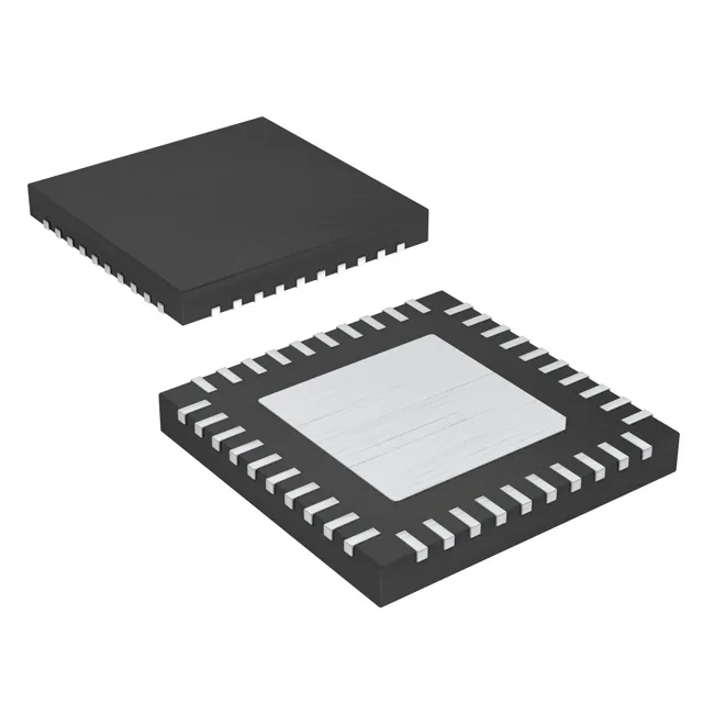
Analog Devices MAX16930BATLS/V+, Automotive Grade, Buck-Boost Controller, 3 Outputs, 2 Phases, 3.5-42V Input, 1-2.2MHz, 40-TQFN (6x6), Tube.

$11.77Ref. price · indicative, final on quote
Packaging40-WFQFN Exposed Pad
StockContact for availability
Lead timeIn Stock wk
MOQ1 pcs
  • 100% new & originalTraceable channels only — no refurbs, no pulls, no remarked parts.
  • Date & lot codes on quoteStated per line before you commit; label photos on request.
  • MSL-compliant ESD packingMoisture-sealed bags with indicator cards; reels photo-verified.
  • PayPal buyer protectionPay by T/T, PayPal or Payoneer — card payments covered end to end.

Specifications

MAX16930BATLS/V+ Technical Specifications
ParameterValue
Output typeTransistor Driver
Mounting typeSurface Mount
Voltage - supply (Vcc (Vdd))3.5V ~ 42V
Frequency1MHz ~ 2.2MHz
Number of outputs3
Output phases2
Duty cycle95%
Operating temperature-40°C ~ 125°C (TJ)
GradeAutomotive
PackageTube
FunctionStep-Up, Step-Down
TopologyBuck, Boost
Clock syncYes
QualificationAEC-Q100
Case40-WFQFN Exposed Pad
Control featuresEnable, Frequency Control, Power Good
Output configurationPositive
Synchronous rectifierYes

Product details

Active production, automotive-qualified dual buck-boost controller

The MAX16930BATLS/V+ is an active-production Analog Devices dual-output controller that steps up or steps down from a 3.5 V to 42 V supply rail — the wide input range covers 12 V nominal automotive bus with cold-crank dips and load-dump transients without an external pre-regulator.

What the key ratings mean for the BOM decision

Three outputs with two switching phases let the controller drive a dual-rail power tree — one buck for the MCU core and one buck/boost for the sensor or actuator supply — from a single IC, reducing the component count and PCB area compared to a discrete two-converter solution. The 1 MHz to 2.2 MHz switching-frequency range allows the designer to trade off inductor size against switching losses; at 2.2 MHz the external inductor and output capacitors shrink, which matters in the 40-TQFN (6x6 mm) footprint where board space is tight. Synchronous rectification is built in — no external Schottky catch diode needed, which saves a component and improves efficiency at high switching frequencies. Control features include Enable, Frequency Control, and Power Good — the PG flag simplifies the power-up sequencing handshake with the downstream MCU or SoC without a separate supervisor IC.