What this boost converter does on your board
The MAX1677EEE+: It generates a positive adjustable or fixed output rail from an input as low as 0.7 V up to 5.5 V — meaning it can run from a single-cell alkaline battery down to its end-of-discharge voltage, or from a Li-ion cell across its full range. With two independent outputs, one channel can be set to a fixed 3.3 V (or 1.25 V / 2.5 V) while the other is adjustable up to 28 V — useful for generating a low-voltage core rail alongside a high-bias supply for LCD bias or sensor excitation.
The internal switch is rated for 350 mA peak current — this is the limit on the inductor current, not the output current. In a typical boost from 3 V to 5 V at 300 kHz, the available output current is roughly 200 mA to 250 mA, depending on inductor losses and duty cycle. The 300 kHz switching frequency keeps the inductor physically small, suitable for space-constrained portable designs. Synchronous rectification replaces the usual Schottky output diode with a low-Rds(on) FET, boosting efficiency by 3–5% at light loads compared to a non-synchronous boost — a meaningful gain in battery-powered applications where every milliwatt counts.
Temperature grade and deployment context
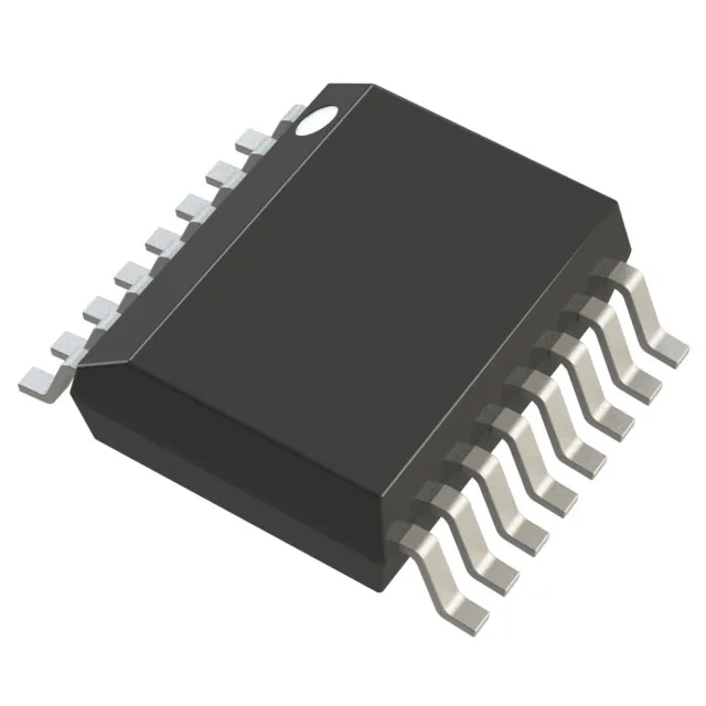
The 16-SSOP package with 0.154" body width fits on a standard two-layer PCB with reasonable fan-out for the switch node and feedback traces. ROHS3 compliance means no RoHS exemption issues for EU shipments or global supply chains — the part ships with full material declaration traceable to the manufacturer.
Active lifecycle — sourcing posture
It remains a current-production part suitable for new designs and ongoing BOM positions. Sourced and quoted to order through authorized and independent distribution; availability and current pricing confirmed at RFQ time.