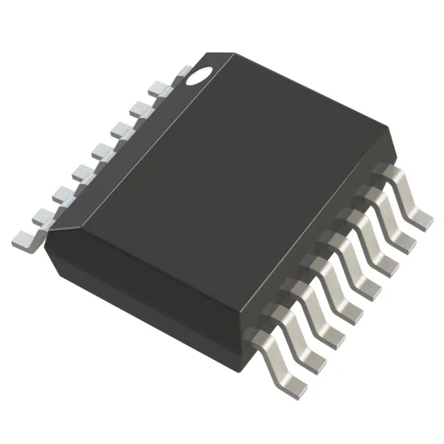
Controller parametrics and supply range
The MAX1654EEE+ is a current-mode step-down (buck) controller that drives external N-channel MOSFETs via a transistor-driver output. It operates from a 4.5V to 30V supply rail, covering 5V, 12V, and 24V industrial buses as well as battery-powered systems. Switching frequency is pin-selectable between 150 kHz and 300 kHz, and the part supports external clock synchronization to align switching edges with other converters in the system — useful for avoiding beat-frequency ripple in multi-rail designs. The controller includes an enable input and a soft-start feature for controlled ramp-up, plus a synchronous rectifier driver to improve efficiency by replacing the freewheeling diode with a low-Rds(on) MOSFET.
Output configuration and duty cycle
Two outputs are available — the controller can drive two independent converter stages or a dual-phase rail for higher output current with reduced ripple. The output configuration is positive, and the maximum duty cycle reaches 98%, allowing near-dropout operation when the input voltage is close to the output. The single-phase topology keeps the external component count low: one inductor, one sense resistor, and a pair of MOSFETs per output. The 16-pin SSOP (3.90 mm width) or QSOP package fits compact PCB layouts typical of space-constrained industrial and telecom power stages.
Temperature grade and deployment context
The controller itself does not carry the pass-element heat — the external MOSFETs and inductor handle the thermal load, so board layout and airflow determine the final power capability.