What the key ratings mean for the BOM decision
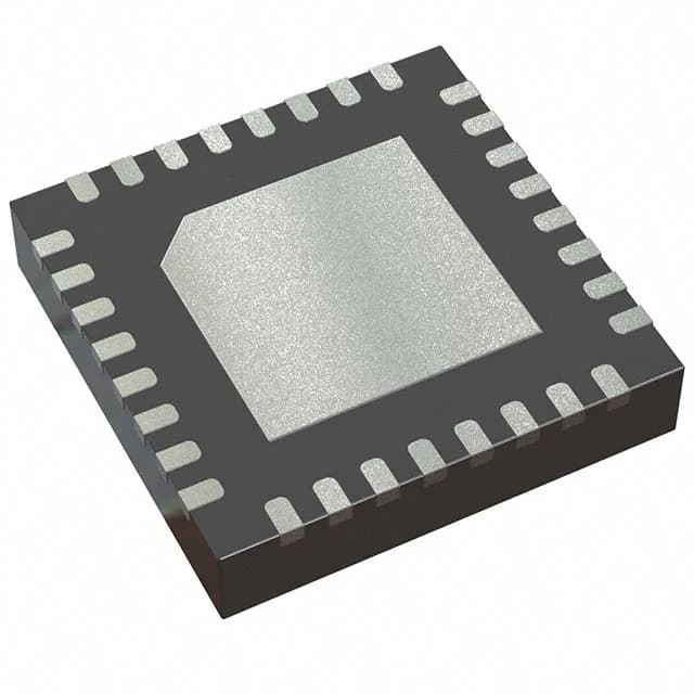
Switching frequency is programmable from 300kHz to 1MHz, with clock sync available. A lower frequency (300-500kHz) reduces switching losses and suits higher step-down ratios; 1MHz lets you shrink the output inductor and capacitor, saving board area at the cost of slightly higher FET gate-drive loss. The synchronous rectifier is built in, so no external Schottky catch diode is needed — the low-side MOSFET handles the freewheeling interval. Control features include current limit, enable, and power-good output. The power-good flag is open-drain and asserts when the output is within regulation — useful for sequencing or fault reporting to a CPLD or supervisor. The enable pin lets the system hold the controller off until the input rail is stable. The 32-TQFN (5x5mm) package with exposed pad requires a thermal land on the PCB. The exposed pad must be soldered to a copper plane for heat spreading; a via array under the pad to an inner ground plane is standard practice. The package is surface-mount, compatible with standard reflow profiles.
Temperature grade and deployment environment
Rated for -40°C to 85°C ambient, this controller fits industrial control, base-station power, networking equipment, and outdoor telecom enclosures. It is not qualified to AEC-Q100, so it is not aimed at automotive under-hood or chassis domains. The 95% maximum duty cycle allows operation close to dropout — useful when the input rail sags under load.
Lifecycle and sourcing posture
The MAX15301AA02+CJK is listed as Active and ROHS3 compliant. For a production BOM line that needs PMBus telemetry on a 12V buck rail, this part is a current-design fit with no LTB risk.