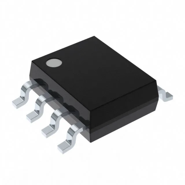
Analog Devices MAX15013AASA+ — DC-DC Power Modules

MAX15013AASA+ Half-Bridge Gate Driver, 2A Peak, 8-SOIC

MPNMAX15013AASA+
End of Life

Analog Devices MAX15013AASA+ half-bridge gate driver, N-Channel MOSFET, non-inverting, 2A peak output, 8V-12.6V supply, 8-SOIC package, Tube.

$8.22Ref. price · indicative, final on quote
Packaging8-SOIC (0.154", 3.90mm Width)
StockContact for availability
Lead timeIn Stock wk
MOQ1 pcs
  • 100% new & originalTraceable channels only — no refurbs, no pulls, no remarked parts.
  • Date & lot codes on quoteStated per line before you commit; label photos on request.
  • MSL-compliant ESD packingMoisture-sealed bags with indicator cards; reels photo-verified.
  • PayPal buyer protectionPay by T/T, PayPal or Payoneer — card payments covered end to end.

Specifications

MAX15013AASA+ Technical Specifications
ParameterValue
Gate typeN-Channel MOSFET
Input typeNon-Inverting
Channel typeIndependent
Mounting typeSurface Mount
Voltage8V ~ 12.6V
Logic voltage - VIL, VIH0.8V, 2V
High side voltage - max (Bootstrap)175 V
Current - peak output (Source, sink)2A, 2A
Operating temperature-40°C ~ 150°C (TJ)
PackageTube
Case8-SOIC (0.154\", 3.90mm Width)
Number of drivers2
Driven configurationHalf-Bridge
Rise (Fall time)65ns, 65ns

Product details

Half-bridge driver with 2 A peak drive and 175 V bootstrap rating

The MAX15013AASA+ is a half-bridge gate driver from Analog Devices designed to drive two N-channel MOSFETs in an independent-channel configuration. It delivers 2 A peak source and sink current, which means it can charge and discharge the gate capacitance of medium-power MOSFETs quickly enough to keep switching losses under control in a 100-500 kHz DC-DC converter. The high-side bootstrap supply is rated to 175 V, so the driver supports bus voltages up to that level in a half-bridge topology — suitable for 48 V telecom rectifiers, 72 V industrial bus converters, or 120 V auxiliary supplies. The 8 V to 12.6 V supply range on the low side matches standard bias rails from a 12 V auxiliary or a regulated 10 V rail.

Switching speed and temperature envelope

Typical rise and fall times are 65 ns each into the rated load — the propagation delay symmetry between the high-side and low-side channels determines the dead-time margin you need in the PWM controller to avoid shoot-through. The 8-SOIC package (0.154" body width) dissipates heat through the leadframe — the thermal resistance junction-to-ambient is around 120°C/W in still air, so the 2 A peak drive at high frequency will need attention to PCB copper area and airflow if the ambient exceeds 85°C.

Frequently asked questions

What is the closest pin-compatible alternative to MAX15013AASA+?

No official pin-compatible cross-reference or second-source is listed in the manufacturer records for this part. The MAX15013AASA+ is a unique order code within the Analog Devices gate driver portfolio — any functional equivalent would require a board-level review of pinout, bootstrap rating, and drive current.