Switching frequency and duty-cycle limits — what they mean for the transformer
The 50% duty-cycle ceiling is the headline constraint for a flyback design. It limits the maximum on-time of the primary switch to half the switching period, which directly sets the volt-second product on the transformer primary. For a given input voltage and turns ratio, this caps the output voltage the controller can regulate. The wide switching frequency range — 25kHz to 625kHz — gives the designer flexibility: lower frequencies reduce switching losses but require larger magnetics; higher frequencies shrink the transformer and output capacitor but increase gate-drive losses and may complicate EMI filtering. The controller does not include clock sync, so multiple converters on the same board need external frequency dithering or careful layout to avoid beat-frequency noise.
Active lifecycle — no end-of-life risk for new designs
The MAX15001AEUB+ carries an Active product status and is ROHS3 compliant. There is no last-time-buy notice or NRND flag. For a BOM line that needs a boost or flyback controller in the 10-uMAX package, this part is a safe selection for production — no imminent obsolescence risk, and the ROHS3 compliance covers current and foreseeable regulatory requirements.
Package and mounting — 10-uMAX/uSOP footprint
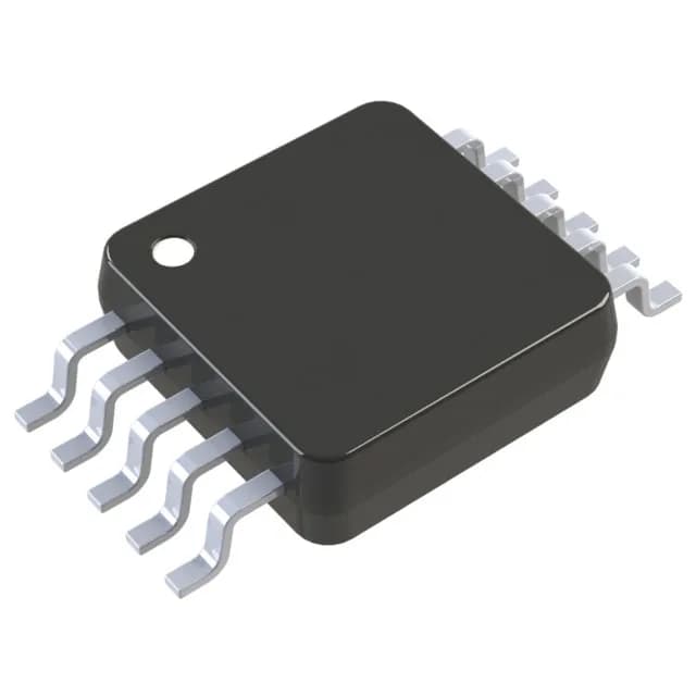
The MAX15001AEUB+ is supplied in a 10-pin TFSOP/MSOP package (0.118-inch body width, 3.00mm width) with the supplier device package designated as 10-uMAX/uSOP. It is a surface-mount device. The small footprint suits space-constrained designs, but the thermal dissipation path is through the leads only — no exposed pad. For continuous operation near the 85°C upper limit, ensure adequate copper area on the PCB to keep the junction temperature within the die's rating. The Enable control feature allows the controller to be shut down externally, which can be used for sequencing or fault logic.