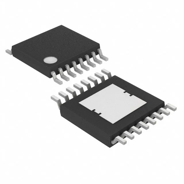
3 A continuous output in a 16-TSSOP exposed-pad package
The MAX14871EUE+T: The 3 A figure is the nominal continuous rating at the package's thermal limit — the exposed pad on the 16-TSSOP-EP must be soldered to a PCB copper plane to pull heat from the output stage. Without adequate thermal vias to an inner-layer ground pour, the junction temperature rise above ambient will limit the usable output current well below 3 A.
PWM interface and half-bridge output for bidirectional control
The driver accepts a standard PWM input from a microcontroller or timer — the integrated control and power stage translates the duty cycle into motor voltage. Two half-bridge outputs allow forward, reverse, and brake modes for a single brushed DC motor. The Bi-CMOS process keeps quiescent current low enough that the driver can stay powered in a standby system without draining the supply. At the 36 V maximum, the driver covers 24 V industrial buses and 24 V nominal battery systems with headroom for transients.
150°C junction temperature and general-purpose application scope
The 150°C TJ ceiling is the absolute maximum — the actual die temperature at 3 A output depends on the PCB's thermal resistance, which the datasheet's thermal model (page 7 of the datasheet) calculates from the exposed-pad copper area. Analog Devices lists the part as Active with ROHS3 compliance. No end-of-life notice or last-time-buy window is announced.