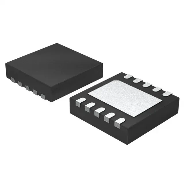
Analog Devices MAX13256ATB+T — DC-DC Power Modules

MAX13256ATB+T Analog Devices Half-Bridge Driver, 850mA

MPNMAX13256ATB+T
End of Life

Analog Devices MAX13256ATB+T half-bridge gate driver IC, 850 mA per channel, 8 V to 36 V supply, 600 mOhm LS / 1 Ohm HS Rds(on), internal oscillator, status flag, watchdog timer, 10-TDFN-EP package.

$8.03Ref. price · indicative, final on quote
Packaging10-WFDFN Exposed Pad
StockContact for availability
Lead timeIn Stock wk
MOQ1 pcs
  • 100% new & originalTraceable channels only — no refurbs, no pulls, no remarked parts.
  • Date & lot codes on quoteStated per line before you commit; label photos on request.
  • MSL-compliant ESD packingMoisture-sealed bags with indicator cards; reels photo-verified.
  • PayPal buyer protectionPay by T/T, PayPal or Payoneer — card payments covered end to end.

Specifications

MAX13256ATB+T Technical Specifications
ParameterValue
Load typeInductive
Mounting typeSurface Mount
Voltage - load8V ~ 36V
Voltage8V ~ 36V
Current - output (Channel)850mA
InterfaceLogic
Operating temperature-40°C ~ 150°C (TJ)
PackageTape & Reel (TR); Cut Tape (CT)
FeaturesInternal Oscillator, Status Flag, Watchdog Timer
TechnologyPower MOSFET
ApplicationsTransformers
Rds on600mOhm LS, 1Ohm HS
Case10-WFDFN Exposed Pad
Fault protectionCurrent Limiting, Over Temperature, UVLO
Output configurationHalf Bridge (2)

Product details

Half-bridge driver with integrated oscillator and watchdog

The MAX13256ATB+T is a half-bridge driver IC from Analog Devices, built with power MOSFET technology and rated for 850 mA per channel in a half-bridge (2) output configuration. It integrates an internal oscillator, a status flag, and a watchdog timer — features that let it drive isolated transformer loads with minimal external timing components while monitoring for fault conditions.

Supply range and on-resistance — what they mean for the transformer drive

The device operates from an 8 V to 36 V supply rail, covering the common industrial and telecom voltage range without an external regulator. Typical on-resistance is 600 mOhm for the low-side FET and 1 Ohm for the high-side FET — the asymmetry means the LS path dissipates less conduction loss, so the dead-time budget should account for the HS FET's higher Rds(on) to avoid shoot-through during the cross-conduction interval.

Protection and monitoring — why the status flag and watchdog matter

Fault protection includes current limiting, over-temperature shutdown, and under-voltage lockout (UVLO) — the UVLO threshold prevents the half-bridge from operating with a rail too low to fully enhance the internal MOSFETs, which would otherwise drive them into the linear region and burn excess power. The watchdog timer and status flag give the system a way to detect a stalled or missing clock and assert a clean shutdown, useful when the driver is the primary clock source for an isolated converter.

Frequently asked questions

What is the MAX13256ATB+T's output current rating?

It is rated for 850 mA per channel in a half-bridge (2) output configuration. The low-side FET has a typical on-resistance of 600 mOhm, and the high-side FET is 1 Ohm.

What supply voltage does the MAX13256ATB+T need?

The supply voltage range is 8 V to 36 V for both the load and the logic supply, simplifying the power rail design in systems that already have a 12 V, 24 V, or 36 V bus.