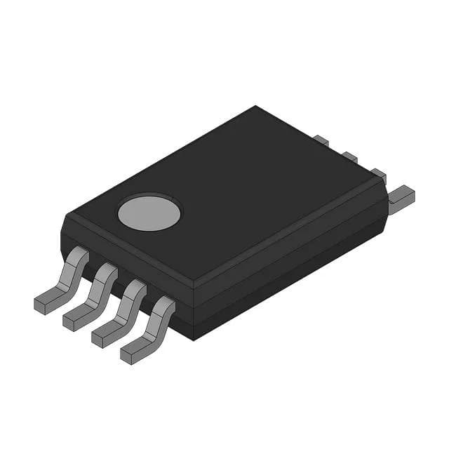
Analog Devices MAX1286EKA+T — DC-DC Power Modules

MAX1286EKA+T 12-bit SAR ADC, 150k SPS, SOT-23-8

MPNMAX1286EKA+T
End of Life

Maxim MAX1286EKA+T, 12-bit SAR ADC, 150k samples per second, 2-input single-ended, SPI data interface, SOT-23-8 surface mount package, 5V analog/digital supply, -40°C to 85°C operating temperature.

$12.32Ref. price · indicative, final on quote
PackagingSOT-23-8
StockContact for availability
MOQ1 pcs
  • 100% new & originalTraceable channels only — no refurbs, no pulls, no remarked parts.
  • Date & lot codes on quoteStated per line before you commit; label photos on request.
  • MSL-compliant ESD packingMoisture-sealed bags with indicator cards; reels photo-verified.
  • PayPal buyer protectionPay by T/T, PayPal or Payoneer — card payments covered end to end.

Specifications

MAX1286EKA+T Technical Specifications
ParameterValue
Input typeSingle Ended
Mounting typeSurface Mount
Reference typeExternal
Voltage - supply, analog5V
Voltage - supply, digital5V
Number of inputs2
InterfaceSPI
Operating temperature-40°C ~ 85°C
PackageTape & Reel (TR); Cut Tape (CT)
ArchitectureSAR
ConfigurationS/H-ADC
Number of bits12
CaseSOT-23-8
Ratio - s (H:ADC)1:1
Number of a (D converters)1
Sampling rate (Per second)150k

Product details

12-bit SAR ADC in a SOT-23-8 — what the specs mean for your board

The Maxim MAX1286EKA+T is a 12-bit successive-approximation-register (SAR) analog-to-digital converter with a single-ended input configuration, two input channels, and a 1:1 sample-and-hold to ADC ratio. It samples at 150k samples per second over the SPI bus, making it a compact choice for embedded data acquisition where board area is tight. The 5V analog and digital supply rails are shared — both run on the same 5V rail, so there is no separate AVDD/DVDD split to manage. The SOT-23-8 package (also listed as Supplier Device Package SOT-23-8) keeps the footprint small. Operating temperature spans -40°C to 85°C, the industrial grade.

150k samples per second — where it fits and where it doesn't

At 150k samples per second, this ADC handles slow-to-moderate signals: temperature, pressure, current sense, potentiometer feedback, and general-purpose analog monitoring. It will not capture audio bandwidth or fast transient events — those need a higher sample rate or a pipelined architecture. The SAR architecture gives cycle-by-cycle conversion with no pipeline delay, so each sample is a fresh measurement. That matters for multiplexed inputs where you need a settled reading per channel without waiting for a pipeline flush. The SPI data interface runs at whatever clock rate the master provides, up to the ADC's maximum. No parallel bus, no extra I/O pins — just three or four wires (SCLK, DIN, DOUT, /CS) to the microcontroller.

Supply and reference — the 5V constraint

Both analog and digital supplies are 5V. The digital supply powers the SPI interface logic, so the SPI output levels are 5V CMOS. The reference is external (Reference Type: External), so the full-scale range is set by the voltage applied to the REF pin.

Lifecycle and sourcing

The MAX1286EKA+T carries an Active product status and is ROHS3 compliant. For a BOM line, this is a low-risk fit for both prototype builds and production runs.

Frequently asked questions

Is MAX1286EKA+T equivalent to MAX1287?

The MAX1286 and MAX1287 are closely related parts in the same family. The key difference is the number of input channels: the MAX1286 has 2 single-ended inputs, while the MAX1287 typically offers a different channel count or configuration. Verify the exact pinout and channel count in the datasheet before substituting.

What is the maximum sample rate of MAX1286EKA+T?

The maximum sampling rate is 150k samples per second (150 kSPS). This is the throughput for continuous conversions over the SPI interface at the rated clock speed.

Can MAX1286EKA+T work with 3.3V logic?

The digital supply is specified at 5V, so the SPI logic levels are 5V CMOS. Direct connection to a 3.3V microcontroller may exceed the MCU's input voltage tolerance. A level shifter or voltage divider on the SPI output lines is recommended when interfacing with 3.3V logic.