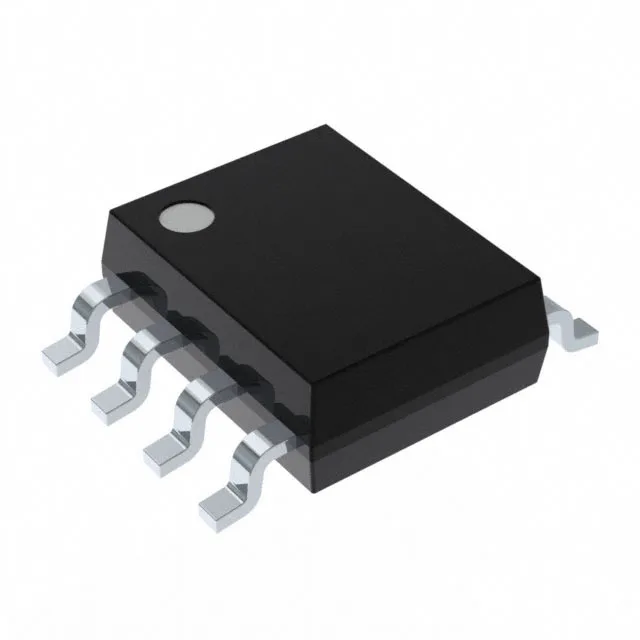
12-bit SAR ADC with a 73k sample rate and a single 2.7-3.6 V rail
The MAX1240CCSA+: The SAR architecture delivers a 1:1 S/H:ADC ratio, meaning the sample-and-hold captures the input once per conversion cycle, with no pipeline latency — the digital output corresponds to the voltage at the instant the hold command fires. That matters when your signal has fast edges and you need a deterministic sample point, not a moving average across several clock cycles. That simplifies the power tree: one 3.3-V LDO and a decoupling cap at the supply pin, and you are done. The reference can be either the internal bandgap or an external voltage applied to the REF pin, so you can trade absolute accuracy against bill-of-materials cost depending on the channel count.
SPI data interface and 8-SOIC footprint — what the package tells the layout engineer
Data moves over a standard SPI bus — the ADC presents the conversion result on the DOUT pin, clocked by the master's SCLK. The SPI interface keeps the pin count low (8 pins total in the SOIC package) and lets the ADC sit on a shared bus with other SPI peripherals as long as the chip-select line is gated. That covers most bench instruments, data loggers, and industrial control panels that live indoors, but it will not survive under-hood automotive or a freezer warehouse. If the ambient around the ADC exceeds 70°C, the internal reference drifts and the conversion linearity degrades; the datasheet's min/max limits apply only inside that envelope.
If you are qualifying a second source, you would need to evaluate a functionally equivalent SAR ADC from another vendor and spin the PCB layout to match the alternate pinout.