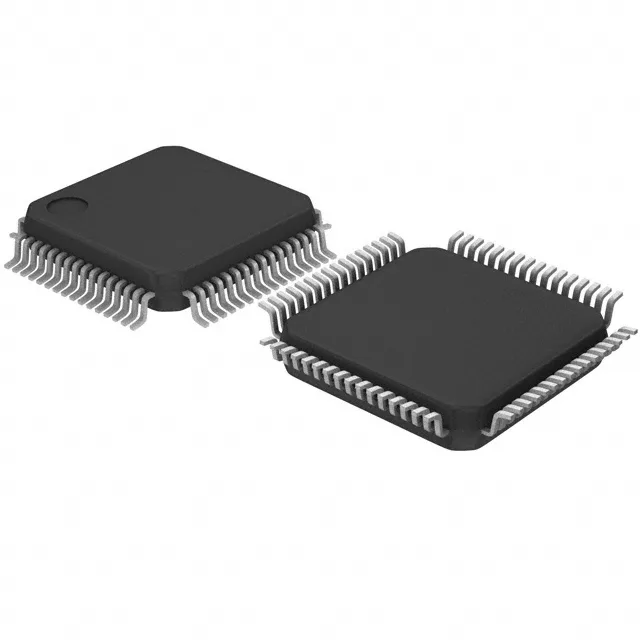
Analog Devices LT8708ILWE#PBF — Microcontrollers & Processors (MCU / MPU / DSP)

LT8708ILWE#PBF Buck-Boost Controller, 80V, 2.8-80V Input

MPNLT8708ILWE#PBF
End of Life

Analog Devices LT8708ILWE#PBF 80V bidirectional buck-boost controller, 2.8V to 80V supply, 100kHz to 400kHz switching, 64-LQFP exposed pad, tray.

$16.9Ref. price · indicative, final on quote
Packaging64-LQFP Exposed Pad
StockContact for availability
Lead timeIn Stock wk
MOQ1 pcs
  • 100% new & originalTraceable channels only — no refurbs, no pulls, no remarked parts.
  • Date & lot codes on quoteStated per line before you commit; label photos on request.
  • MSL-compliant ESD packingMoisture-sealed bags with indicator cards; reels photo-verified.
  • PayPal buyer protectionPay by T/T, PayPal or Payoneer — card payments covered end to end.

Specifications

LT8708ILWE#PBF Technical Specifications
ParameterValue
Output typeTransistor Driver
Mounting typeSurface Mount
Voltage - supply (Vcc (Vdd))2.8V ~ 80V
Frequency100kHz ~ 400kHz
Number of outputs1
Output phases2
Duty cycle80%
Operating temperature-40°C ~ 125°C (TJ)
PackageTray
FunctionStep-Up/Step-Down
TopologyBuck-Boost
Clock syncYes
Case64-LQFP Exposed Pad
Control featuresEnable
Output configurationPositive
Synchronous rectifierYes

Product details

80V bidirectional buck-boost — the input range decides the system

The LT8708ILWE#PBF is an 80V bidirectional buck-boost controller from Analog Devices, built for systems where the input rail swings above and below the output. The 2.8V to 80V supply range covers multi-cell battery stacks, 12V/24V automotive nets with cold-crank dips, and industrial 48V rails — all without a pre-regulator. It regulates a single positive output using a 2-phase buck-boost topology with synchronous rectification, which means the low-side FETs also conduct — efficiency holds up across the full input-to-output ratio, not just in buck or boost mode alone.

Switching frequency and duty cycle — sizing the magnetics

A 100kHz design uses a larger inductor but keeps switching losses low; 400kHz shrinks the magnetics at the cost of higher FET gate-drive dissipation. The 80% max duty cycle caps the step-down ratio — at 5V input, the minimum achievable output is about 6.25V before the controller skips cycles. The 64-LQFP exposed pad package is the thermal interface for the controller's internal gate-drive losses. The PCB layout must connect the pad to a copper plane — the datasheet's recommended footprint and via pattern are not optional for full load operation at 125°C junction temperature.

Lifecycle and compliance — design-in safe, no EOL clock ticking

ROHS3 compliant, so it clears EU and global regulatory requirements without an exemption expiry. For a BOM that already uses the LT8708EUHG#PBF, the ILWE variant is the same silicon in a tray-packed LQFP instead of tube — the electrical ratings are identical, so no re-spin is needed. The only difference is the shipping medium and the package marking.

Frequently asked questions

What is the difference between LT8708ILWE#PBF and LT8708EUHG#PBF?

Both are the same 80V bidirectional buck-boost controller die. The ILWE variant ships in a tray-packed 64-LQFP-EP, while the EUHG variant comes in tube packaging. Electrical specifications are identical — the choice is a logistics decision, not a design one.

What supply voltage range does LT8708ILWE#PBF support?

The Vcc/Vdd range is 2.8V to 80V. This covers single-cell Li-ion up to 80V industrial buses. The controller regulates a single positive output using a buck-boost topology, so the output can be above, below, or equal to the input.