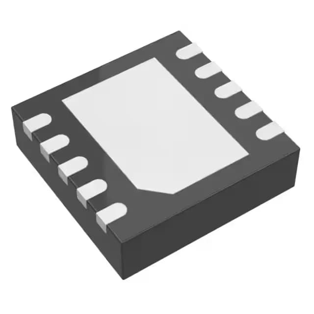
Analog Devices LT1991IDD#PBF — Logic ICs

LT1991IDD#PBF Programmable Gain Amplifier, 560 kHz

MPNLT1991IDD#PBF
End of Life

Analog Devices LT1991IDD#PBF, Programmable Gain Amplifier, 1 Circuit, Rail-to-Rail Output, 560 kHz Gain Bandwidth, 110 kHz -3dB Bandwidth, 0.12V/µs Slew Rate, 2.7V to 36V Supply, 25 µV Offset, 130 µA Supply Current, 10-WFDFN Exposed Pad Package, -40°C to 85°C.

$3.55Ref. price · indicative, final on quote
Packaging10-WFDFN Exposed Pad
StockContact for availability
MOQ1 pcs
  • 100% new & originalTraceable channels only — no refurbs, no pulls, no remarked parts.
  • Date & lot codes on quoteStated per line before you commit; label photos on request.
  • MSL-compliant ESD packingMoisture-sealed bags with indicator cards; reels photo-verified.
  • PayPal buyer protectionPay by T/T, PayPal or Payoneer — card payments covered end to end.

Specifications

LT1991IDD#PBF Technical Specifications
ParameterValue
Output typeRail-to-Rail
Mounting typeSurface Mount
Amplifier typeProgrammable Gain
Voltage - input offset25 µV
Voltage - supply span2.7 V
Current - supply130µA
Current - input bias2.5 nA
Current - output (Channel)21 mA
Operating temperature-40°C ~ 85°C
-3db bandwidth110 kHz
Gain bandwidth product560 kHz
PackageBulk
Slew rate0.12V/µs
Case10-WFDFN Exposed Pad
Number of circuits1

Product details

Programmable-gain amplifier for precision sensor front-ends

It combines a 560 kHz gain-bandwidth product with a 110 kHz -3 dB bandwidth, a 0.12 V/µs slew rate, and rail-to-rail output swing — characteristics that suit it for conditioning signals from strain gauges, thermocouples, and bridge sensors where the gain needs to be set by external resistors rather than a fixed topology. The 25 µV input offset voltage and 2.5 nA input bias current keep DC errors low enough that many applications can skip a software calibration step. Supply range from 2.7 V to 36 V means the same part can serve a 3.3 V battery-powered data logger or a 24 V industrial transmitter without a rail converter.

Supply current and output drive — sizing for always-on and loop-powered designs

At 130 µA supply current, the LT1991IDD#PBF fits into power budgets where every microamp counts — think 4-20 mA loop-powered transmitters or battery-backed sensor nodes that stay awake continuously. If the load is purely resistive and the signal bandwidth stays under 110 kHz, the 0.12 V/µs slew rate is sufficient to maintain linearity; for faster edges, a wider-bandwidth PGA would be needed.

Package and thermal — what the 10-DFN exposed pad means for the board

The exposed pad is also the ground return for the die substrate — the layout should connect it to the analog ground plane with a low-impedance path, not leave it floating.

Frequently asked questions

What is the equivalent part for LT1991IDD#PBF?

There is no pin-compatible second source listed for the LT1991IDD#PBF. The AD627ARZ-RL is another instrumentation amp with 80 kHz bandwidth and 50 µV offset, but it lacks the programmable-gain topology. For a direct replacement, stick with the LT1991IDD#PBF.

What is the gain range of LT1991IDD#PBF?

The LT1991 is a programmable gain amplifier whose gain is set by external resistors. The datasheet typical configuration supports gains from 1 to 1000, but the exact range depends on the resistor values chosen. The 560 kHz gain-bandwidth product means the usable bandwidth drops proportionally as gain increases — at a gain of 100, expect roughly 5.6 kHz of usable bandwidth.