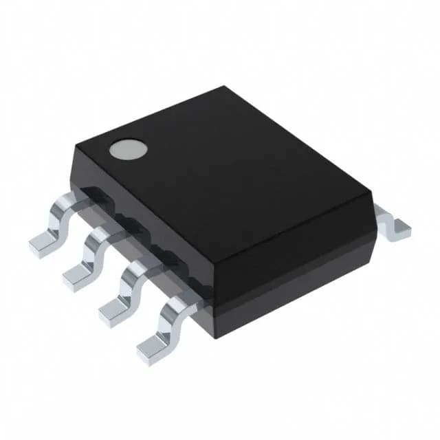
Dual N-channel MOSFET driver with 20ns edges
The Maxim Integrated ICL7667EBA+ is a dual, independent N-channel MOSFET gate driver in an 8-SOIC package. It drives two N-channel MOSFETs with typical rise and fall times of 20ns, making it suited for half-bridge topologies in switch-mode power supplies, motor drives, and DC-DC converters. The supply range of 4.5V to 17V covers standard 5V and 12V bias rails, and the inverting input logic accepts 0.8V VIL and 2V VIH thresholds for direct interface with most PWM controllers.
20ns switching speed — what it means for the power stage
A 20ns rise and fall time (typical) at the gate driver output means the MOSFET transitions quickly through the linear region, reducing switching losses. In a 100kHz to 500kHz switching regulator, this keeps the dead-time budget tight — typically 50ns to 100ns margin is enough to avoid shoot-through. The 20ns edges also limit the gate charge injection into the bootstrap circuit; a 0.1µF bootstrap capacitor is usually sufficient for a 1nF to 10nF gate load. If the layout adds more than 10nH of parasitic inductance in the gate loop, expect some ringing — a small series gate resistor (5Ω to 10Ω) cleans it up without slowing the edge much.
Supply voltage and temperature range
Rated for a supply voltage from 4.5V to 17V, the ICL7667EBA+ runs comfortably on a 5V logic rail or a 12V bias supply. The junction temperature range of 0°C to 150°C (TJ) covers most industrial and telecom environments — the 150°C ceiling allows operation in enclosed power supplies or motor drives where ambient heat pushes the die temperature. The 8-SOIC package's thermal resistance is about 150°C/W (typical for SOIC-8), so at 12V supply and 1A gate charge per cycle, the self-heating stays under 10°C in normal switching.
Active lifecycle — no LTB risk
The ICL7667EBA+ carries an active product status per the manufacturer, with ROHS3 compliance. There is no last-time-buy notice or obsolescence risk for new designs.