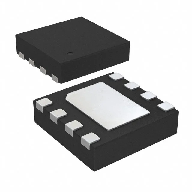
Analog Devices ADP7185ACPZN2.5-R7 — Microcontrollers & Processors (MCU / MPU / DSP)

ADP7185ACPZN2.5-R7 -2.5V 500mA LDO, 8-LFCSP

MPNADP7185ACPZN2.5-R7
End of Life

Analog Devices ADP7185ACPZN2.5-R7 negative linear regulator, fixed -2.5V output, 500mA, 80dB~40dB PSRR (1kHz~1MHz), 8-LFCSP (2x2mm), -40°C~125°C, active.

$5.49Ref. price · indicative, final on quote
Packaging8-UFDFN Exposed Pad, CSP
StockContact for availability
Lead timeIn Stock wk
MOQ1 pcs
  • 100% new & originalTraceable channels only — no refurbs, no pulls, no remarked parts.
  • Date & lot codes on quoteStated per line before you commit; label photos on request.
  • MSL-compliant ESD packingMoisture-sealed bags with indicator cards; reels photo-verified.
  • PayPal buyer protectionPay by T/T, PayPal or Payoneer — card payments covered end to end.

Specifications

ADP7185ACPZN2.5-R7 Technical Specifications
ParameterValue
Output typeFixed
Mounting typeSurface Mount
Voltage - input-5.5V
Voltage dropout0.36V @ 500mA
Voltage - output (Min (Fixed))-2.5V
Current - output500mA
Current - supply7 mA
Current - quiescent900 µA
Operating temperature-40°C ~ 125°C (TJ)
PSRR80dB ~ 40dB (1kHz ~ 1MHz)
PackageTape & Reel (TR); Cut Tape (CT)
Case8-UFDFN Exposed Pad, CSP
Control featuresEnable, Power On Reset
Protection featuresOver Current
Number of regulators1
Output configurationNegative

Product details

Negative rail, 500 mA, 2x2 mm — what the specs mean for the board

The ADP7185ACPZN2.5-R7 is a negative-output LDO from Analog Devices, delivering a fixed -2.5 V at up to 500 mA from a -5.5 V max input rail. This is the part to reach for when you need a clean, regulated negative supply for op-amp rails, ADC reference grounds, or split-supply sensor front-ends — the kind of rail that, if it sags or carries ripple, injects noise straight into the signal chain. The 8-LFCSP (2x2 mm) package with exposed pad means the thermal path runs through the PCB copper, not the air.

PSRR that holds up past 100 kHz

PSRR is specified at 80 dB at 1 kHz, rolling off to 40 dB at 1 MHz. That 40 dB at 1 MHz is the number that matters for a switching regulator feeding this LDO — a 2 MHz buck converter's fundamental ripple at 2 MHz sees about 35 dB of rejection, but its switching harmonics at 4, 6, 8 MHz see progressively less. If the upstream switcher runs at 400 kHz, the fundamental ripple at 400 kHz sees roughly 55 dB of rejection, which is enough to keep the output noise below 10 µV RMS with a typical 10 µF output cap. The dropout voltage is 0.36 V max at 500 mA. That means the input rail must stay below -2.86 V (absolute) to maintain regulation at full load — a -3.3 V rail gives 0.44 V of headroom, which is tight but workable if the -3.3 V rail itself is regulated. A -5 V rail gives 2.14 V of headroom, which is comfortable and keeps the LDO in its high-PSRR region.

Protection features include over-current limiting and a Power-On Reset that holds the output in a known state until the input rail is stable.

Frequently asked questions

What is the PSRR of the ADP7185ACPZN2.5-R7 at 1 MHz?

PSRR is 40 dB at 1 MHz, rolling off from 80 dB at 1 kHz. This means the LDO attenuates a 1 MHz ripple by a factor of 100, which is enough to keep switching noise from a 2 MHz buck converter below 10 µV RMS with a typical output capacitor.

Does the ADP7185ACPZN2.5-R7 drop in for the ADP7185ACPZN2.0-R7 without a board change?

Yes — both parts share the same 8-LFCSP (2x2 mm) package, pinout, and control features (Enable, Power On Reset). The only difference is the fixed output voltage: -2.5 V for this part versus -2.0 V for the sibling. If the downstream load (op-amp, ADC reference) is specified for -2.5 V, the swap is a straight BOM line change with no PCB spin.