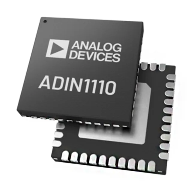
Single-port 10BASE-T transceiver for industrial Ethernet links
It implements the 10BASE-T physical layer, making it the PHY for any industrial controller, sensor node, or gateway that needs a standard twisted-pair Ethernet connection without stepping up to 100BASE-TX complexity or cost. The part operates across three distinct supply rails: a 1V to 1.2V core supply, a 1.71V to 3.46V I/O supply, and a 3.13V to 3.46V transceiver supply. This split-rail architecture lets the digital interface run at 1.8V or 3.3V logic levels while the PHY analog section stays on a clean 3.3V rail, common in mixed-voltage designs.
Supply rails and power-up sequencing
The three supply domains — 1V core, 1.71V–3.46V I/O, and 3.13V–3.46V transceiver — need to be sequenced or co-ramped per the datasheet guidelines. The core rail at 1V is typically generated from the 3.3V input via a local LDO or a small buck converter. A single 3.3V supply with a 1V LDO is the most common BOM arrangement. Because the I/O supply range (1.71V to 3.46V) overlaps the transceiver range, designers can run both from the same 3.3V rail as long as the transceiver supply stays within 3.13V to 3.46V. If the system uses a 1.8V MAC interface, the I/O rail drops to 1.8V while the transceiver rail stays at 3.3V.
Package and layout checklist
The datasheet recommends a 4x4 array of 0.3 mm thermal vias under the pad, connected to a solid ground plane on the inner layers. Without this via stitch, junction temperature rises quickly above 85°C ambient at full duplex traffic. If the moisture-barrier bag has been open longer than the floor-life window (168 hours at ≤30°C/60% RH), bake the devices at 125°C for 24 hours before reflow.
For smaller builds, the cut-tape option is also listed. No pin-compatible second source exists from another manufacturer; this is a single-sourced ADI part.