Reconstruction filter for standard-definition video paths
Its 7.9 MHz -3dB bandwidth is tailored for standard-definition video applications — think composite (CVBS), S-Video, or SDI output stages where you need to clean up the DAC's stair-step artifacts before the line driver. The rail-to-rail output lets it swing the full video signal without headroom issues at 3.3 V single supply, which matters when the DAC reference is also 3.3 V and you cannot afford a clipping artifact on sync tips.
Supply range and current budget
Runs from a single 2.5 V to 3.6 V rail, drawing 4.7 mA typical supply current. No dual supplies needed — one clean 3.3 V rail and a 1 µF decoupling cap at the pin is the usual recipe. At 4.7 mA it is not a micropower part, but for a video filter in a camera module or set-top box that current is a rounding error in the total system budget.
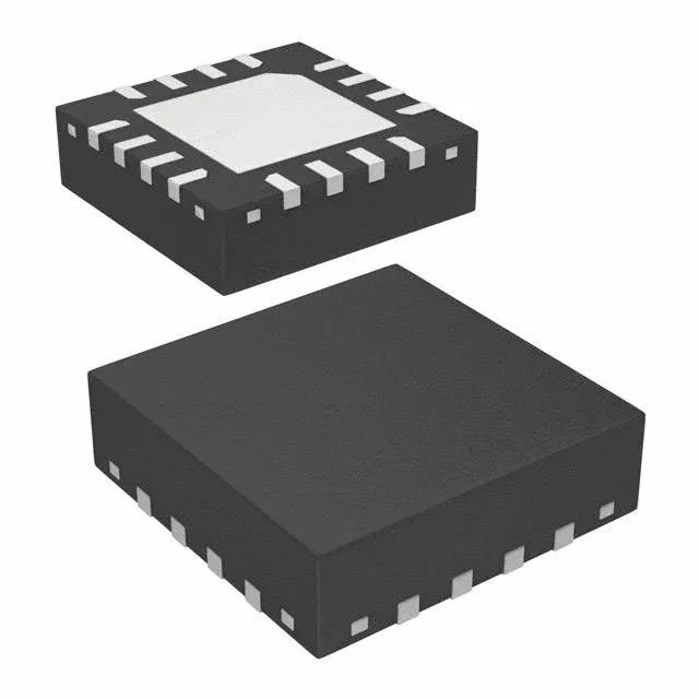
The 16-LFCSP-UQ (3x3) package is a 0.5 mm pitch QFN-style land pattern. If your reflow profile is set for standard lead-free, the 3x3 mm body reflows cleanly; just watch the paste coverage on the center pad to avoid voids that lift the part during wave-solder.
No PCN or obsolescence letter has been issued for this order code as of the current date.
What the 7.9 MHz bandwidth means for your video path
The 7.9 MHz -3dB bandwidth is the key selection parameter. Standard-definition video (PAL/NTSC) has a luminance bandwidth around 5-6 MHz; this filter passes that cleanly while rolling off above 7.9 MHz to suppress the DAC's sampling images. If you are feeding a 1080p HDMI encoder or a VGA DAC, the 7.9 MHz corner is too low — you would alias the higher-frequency content. But for CVBS, S-Video, or SD-SDI outputs this is the right pole. The single-pole roll-off shape means the stopband attenuation is modest; if you need sharper rejection at 27 MHz (the DAC clock), cascade a second-order passive LC after this stage.